Amp discovery!
1 ...
45678910
1 ...
45678910
|
Administrator
|
it will not put out enough amperage to power the preamp and the power amp board. also, that board is 100watt at 4ohm i believe, not 2ohm. i've used the same board, and run it through an 8ohm 4x12 cabinet and it's closer to 70watts at 8ohm, and it's fucking loud.
the wiring you have shown will work, but you're only using 1 of the model t preamp channels as the input to the channel on the left side of the board isn't connected to anything. also, make sure the output jack does not does not have the sleeve connected to ground, which you show correctly, but not sure what style of jack you plan on using. |
|
Ahhh, OK - I understand now about not enough amperage to power both. Thanks. I'll add a power supply...and if you don't mind my asking, what 24V power supply would you recommend? Thanks man!
|
|
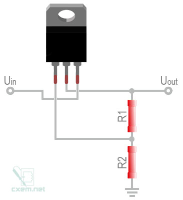
In addition to a suitable/recommended open frame 24V power supply, when you made your voltage divider board with the voltage regulator for the indicator, did you wire it like the attached diagram?
 Thanks! |
|
Administrator
|
hey man i believe the amp can draw as much as 3Amps, so you're power source has to put out more than that, because the circuit will draw only what it needs, and each circuit will draw for the single power source. there's multiple ways to get 24VDC to the circuits. i used an LM350 for the voltage regulator, and calculated the resistor values to get the voltage i wanted, and i use the diagram in the data sheet.
i cant give everything away on how i did what i did, because i spent a lot of time trying to figure it all out and get it to work right. |
|
Administrator
|
In reply to this post by spacefuzz74
Check out something like this
https://rover.ebay.com/rover/0/0/0?mpre=https%3A%2F%2Fwww.ebay.com%2Fulk%2Fitm%2F263532678177 What do you need the regulator for? |
|
Thanks Rocket88! I do want to apologize for asking 5 million questions...I tend to get a little over eager sometimes when I just need to calm myself and figure some things out on my own. Your help is greatly appreciated!
Travis - I was going to use the regulator to bring the 24V down to an acceptable voltage for the indicator LED...but I think a large value CLR will do the trick too. Thanks for the link! |
|
Administrator
|
Hey man nothing to be sorry for. I'm always happy to help, and I didn't mean to come off like a dick or anything. It's more that I've had a bunch of people ask me about how I did it all cause they want to make ones to sell, so I don't want to put all the info out there in one place for someone to make money off my work, you know what I mean. I've literally had people ask my for a schematic and all the details for my build so they can do it themselves and finding out they sell pedals or gear, which is totally not cool. I'll gladly help lead you there.
You can use that regulator to do exactly that. Keep these concepts in mind. 1. You need the right voltage and enough amperage to get it all to work. So some how you need to get from 110/220VAC from the wall down to 24VDC which you can do many ways, but either you have to convert it before you plug into the chassis or find some way to convert it one the chassis. 2. You'll have to split the power to go to all the circuits and have it go to the regulator for the indicator. 3. finally working it all up just think about the flow of the signal and how you want it to go. 4. Remember what I said about heat and choice of jacks. Don't over think it. The hardest part is figuring out how to layout it all out in the chassis, wiring it all up, and building the enclosure. |
|
Thanks! I didn't read you coming off as anything but helpful, and I 100% understand your position. I'm a mechanic by trade, but I love to make noise at home, so after I discovered this group...it's been a blessing and a curse (the curse part is that I have 100 projects I want to build, and it keeps adding up)!
I have a pretty good handle on things, but I'm still learning with every build. You know how it goes I'm sure...6 months ago I would not have even looked into doing an amp like this, but today, I view it as the next project that I can actually accomplish. Every time I visit this site/forum, I'm extremely grateful for the selfless attitude many of the people here have. So, I'm being completely sincere when I say Thank You! It's just great that I can develop a hobby like this on my own, and know that help is always just a few questions away. OK, I'm done! |
|
Hey Rocket88,
I'm working on this project a little bit today, and i went back in this discussion to review instructions/suggestions and one of your comments caught my eye: "You use the + of the in only to the tip of the input jack. The output you need to use both + and -, positive to the tip & negative to the ground. One caveat, you need to use closed jacks that are isolate from the chassis, you do NOT treat the ground lug as actual ground. " I attached 2 drawings, which one is the correct way to wire? i'm a little mixed up here, any insight is much appreciated! 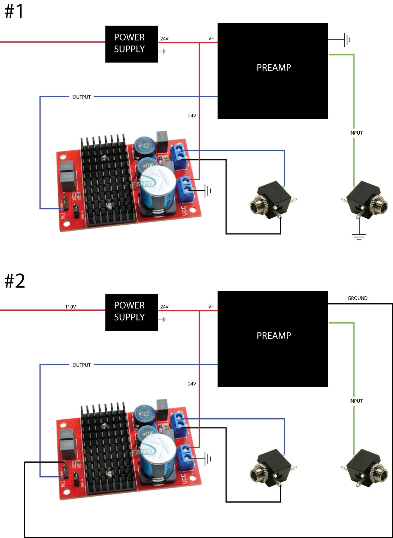
|
|
Administrator
|
Assuming all grounds connect to each other and the enclosure, your diagrams are both the same.
They would both work, but you are not showing an insulated jack for the speaker |
|
thanks! do i just need and insulated jack for the output? or input also...
from Rocket88's comment, i'm understanding that the entire setup should be isolated from the enclosure. "You use the + of the in only to the tip of the input jack. The output you need to use both + and -, positive to the tip & negative to the ground. One caveat, you need to use closed jacks that are isolate from the chassis, you do NOT treat the ground lug as actual ground. " I'm not understanding something here... |
|
Administrator
|
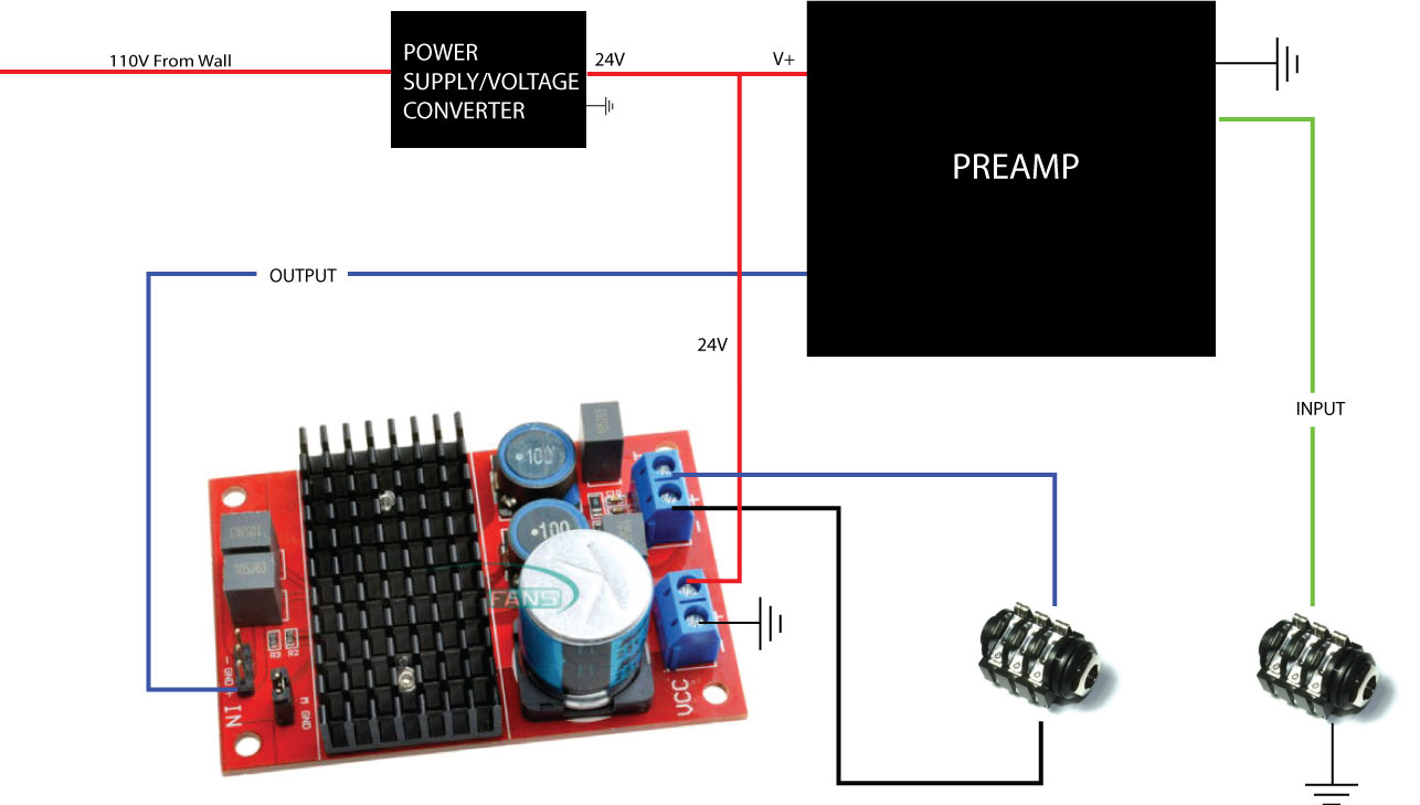
It was a typo, well really a missing word. The output from the power amp you have a + & -. What I meant to say was thaf the negative doesn’t get connected to ground, it connects to the ground lung of the output jack, which is the sleeve. The output jack is isolated it’s not connected to ground. I phrased it poorly trying to make it easier to understand.
So following that, use what you drew for the 1st layout not the bottom. Only use the + on input. The ground and - are for if you’re doing sterio input. |
|
Very cool. Thanks guys! I attached a updated layout showing proper insulated jacks and wiring in case anyone else needs a visual.
|
|
Quick grounding question...
For this amp project, is it good practice to isolate the ground points for the input jack, power supply, pre-amp and power-amp, or not? In other words, 1. Should all of these components share a common ground point within the enclosure? OR 2. Should only some of the components share a common enclosure ground point, and be isolated from the ground point of say, the power-amp? OR 3. Should all the components (input jack, power supply, pre-amp and power-amp) have different ground points within the enclosure? I was planning on grounding everything to the back of the volume pot...but then i started thinking that maybe i should have multiple ground points. Let me know if you have any suggestions or advice! Thanks! |
|
Administrator
|
All grounds connected. In my mini amps I chain them all together so all of them are not on one specific point. I use an open jack for the input so all grounds to the chassis.
|
|
So I ordered some 100watt modules and am disappointed.
All of the heat sinks delaminated and fell off the amplifier chip. Also now that I can see the cjvhip I see several solder pads that have solder bridges. Not sure if this is intentional or not? I haven’t been able to pull up the schematic. 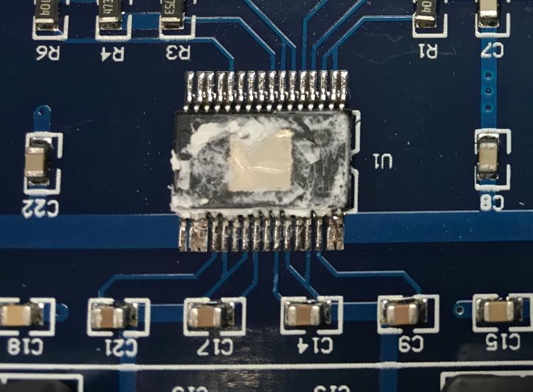
|
|
Solder bridges are probably correct - I have them in mine.
|
|
In reply to this post by Sensei Tim
Same for me! It's the EBAY gamble. Mine arrived like this:
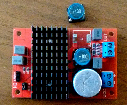
|
|
Administrator
|
Just built another mini amp, a mini orange OR120. I use the 100watt red board ones and have yet to have an issue. It’s odd that the heat sink completely came off the chip, but you can easily reattach if with special double sided tape that’s heat conductive.
|
|
I was thinking I’d use some thermal compound and then 1 or 2 zip ties to hold things in place. The contact area of the top of the chip vs the size/weight of the heat sink is pretty out of proportion. I’m notnsure how well a tiny bit of tapenis goingnto hold the heat sink in place if it’s getting banged around. Sent from Gmail Mobile
|
«
Return to Open Chat
|
1 view|%1 views
| Free forum by Nabble | Edit this page |

