AmpTweaker Tight Metal
123
123
|
This post was updated on .
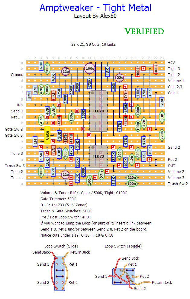
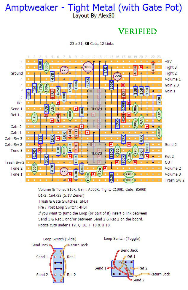
Here are two verified layouts with external or internal (trimmer) gate pot.
There is also a Pre/Post Loop 4PDT switch like in the original. Personally, considering the space the switch takes, I wouldn't include the loop or at least the "Post" option (near OUT). Up to you.   Thanks to Surgeon for verifying it! |
|
Hello mate, did you actually build that pedal?
If you did, how do you like it?
Come with me and walk the longest mile.
|
|
Administrator
|
In reply to this post by Alex
Thanks for sharing the layout by the way albru80, great stuff.
 I've been looking at the schematic and the more I think about it the more I agree about the loops. They're at the beginning (after a buffer) and very end of the circuit, and so no different to just using the Tight Metal with another effect and an order switcher (which I wouldn't want to use anyway). Of course then you need a separate order switcher but personally I'd prefer that than to accommodate features in this pedal which I'd never use and need a bigger box because of them. I'll still do a layout at some point I think, but I'm going to omit the loops entirely. It won't reduce the number of components (other than the extra switch and sockets) but could potentially fit in a 1590B without them. |
|
This post was updated on .
Hi Mark!
Thanks! And thanks again for your great website! I personally wouldn't bother with the loop but that's my taste. I don't even really understand how useful the "post" option could be. I'm sure your external order switcher is a much better idea size-wise. I'm looking forward to seeing your layout! |
|
In reply to this post by Lazybone
Hi Lazybone!
A friend asked me to build him a metal pedal last year. I draw this layout but ended up building something else at the end (can't even remember what!) The layout is not verified but I'm quite sure it follows the schematics correctly. I've check it again before uploading it and the schematics where verified on FSB. I don't know if anybody has built it but let me know if you do. |
|
This post was updated on .
Hello to you mr. albru80,
I'm interested on building this pedal for a friend of mine. It will be my first pedal to try from this site so i want some guidance because I have some questions about it. If you don't mind. My main question is based on the two different layouts you've posted. I believe that the difference is: Layout 1 has on/off on gate while Layout 2 has a pot that can be more specific, if I may. I would like you to clarify this. What is the purpose for the "Gate SW 2, Gate SW 3" on the 2nd Layout (the one with the pot) when I don't have a switch for it? Also, the yello "Gate" component on the first Layout is the switch? Finally, when you say for example "Trash SW 3, Trash SW 2" what do the numbers stand for and why is there missing the "Trash SW 1" ? Sorry for the long Q&A I have going here. I'm just trying to get into the way you guys put the layouts here. My pedal works was all guided from a greek forum and I am more used to that. Thanks a lot in advance. Edit: I found that in USA and Europe, there is a different designation method on pots. In USA A - Audio or Log taper B - Linear taper C - Reverse Log taper G - Graphic taper In Europe A - Linear taper B - Audio or Log taper C - Reverse Log taper G - Graphic taper Which one do you follow?
Come with me and walk the longest mile.
|
|
Hi Lazybone!
In all of this website layouts, "A" stands for Audio (or Logarithmic) and "B" for Linear. About the Amptweaker layouts, both of them have "Trash" & "Gate" switches and a Gate pot. The first one has a Gate trimmer (yellow component) which, in this case, works as an internal pot. It's more of a set and forget kind of pot because it's inside the box and you set it with a screwdriver. If you want a more versatile and easy to reach Gate pot you can have it outside the box with the others (second layout). It works exactly in the same way. It's just up to you. For the switches (still in this case) you could use SPDT or SPST, depending on what you have on hand. The number indicates the lug on the switch that needs to be wired to the board. You can see one of Mark's layouts as an example: http://tagboardeffects.blogspot.it/2014/04/fulltone-fulldrive-ii-mosfet.html You could also check this page from Beavisaudio: http://www.beavisaudio.com/techpages/Switches/ I'm not very good at explaining stuff but I hope you've understood. Maybe Mark or someone else could explain it better. |
|
Hello mate,
Thanks for the response, it was what I needed. So to sum it up, in the Trash example, the Trash SW 1 is missing so it plugs in the ground connections, and that is for the rest of the switches/pots. Am I right?
Come with me and walk the longest mile.
|
|
The missing switches and pots lugs don't need to be connected at all unless specified in the layout.
In this case you leave them empty. That's why you could even use SPST switches and just connect the two lugs you have. You can see it better in the schematics: you just open or close the circuit |
|
Hi, I just made the board and should be able to verify in the next few days...
question: could you verify the number of cuts please? The layout stipulates 40 but I've been over it about 10 times and still only count 39....thx |
|
Hi!
You are right! There are 39 cuts. The program I've used gave me a count of 40 but I must have put 2 cuts in the same place. 39 is correct. I'll change it as soon as possible. Let me know if you manage to verify it. Thanks! |
|
Good to know I'm not going crazy (yet).
I'll post the results as soon as I can. Thanks for the layout and help! |
|
In reply to this post by Alex
Aaaaand verified (the gate pot version that is)!
Thanks for a great layout that wasn't available from Mark. Works great, tONS of gain and the outside gate pot I see as a worthwhile mod... Not sire I'll keep the gate switch though... |
|
Nice one Surgeon. When you are done why don't you put some photos/videos/samples of your creation?
Come with me and walk the longest mile.
|
|
I'm not big on vids and soundclips but pics won't be a problem as usual.
|
|
In reply to this post by Alex
Maybe a couple extra comments after having played it a bit more tonight:
1- the gate pot actually works in reverse "to me". I'd expect the noise level to decrease as the pot is turned clockwise. When wired as per the layout, it's the opposite: full clockwise position yields more noise. I swapped lug 3 gate for lug 1 and it's fine for me. 2- The gate pot as an external adjustment makes a bit less sense than I thought. I may just convert it back to a trimpot for simplicity's sake. It's not that it doesn't work but there really just one sweet spot really, set it where you're more comfortable and forget about it. I may even just omit the switch as well. Without the gating effect the pedal is quite noisy, as would be expected with this amount of gain. Thanks again! |
|
Thanks for verifying it!
I'll reverse the gate pot. It was added as an external on the FSB forum but the original had it as a trimmer. Did you add the loop switch? |
|
Nah, that's another thing I forgot to mention. I really don't see the use of a loop within a pedal, personnaly I'd much rather build a dedicated loop pedal than have one built within a distortion... I'm not saying it'd be useless to everybody but I really don't need it.
|
|
Ehm, about the loop, I am not sure if it is what I thought it is.
I believe it's like the effect loop output that you can find in an amplifier, so that you can send your effects to the distortion, while choosing with a switch if it's gonna be before or after the pedal. Am I right about it? Asking because Surgeon says " personnaly I'd much rather build a dedicated loop pedal" and that made me think of a looper pedal. Is it what I think it is? Thanks.
Come with me and walk the longest mile.
|
|
Yeah, it's a loop as in "effects loop", not as in looper that repeats recorded guitar parts... unless I misunderstand what you mean.
|
«
Return to Booster, OD, Fuzz, Distortion
|
1 view|%1 views
| Free forum by Nabble | Edit this page |

