Awesome Filter!

classic Classic list List threaded Threaded
15 messages Options
Reply | Threaded
Open this post in threaded view
|

Awesome Filter!

Kinski
This filter sounds so nice. Would be useful for some many things. I am trying to make a layout of this, but its just beyond my skills. Anyone willing and able to do this?

https://www.youtube.com/watch?v=yZSkNASlMjM

Here is the filter section that I chopped off from the schematic. Only change that needs to happen is to flip the polarity of C3. Then Input goes to negative side of C3.


Reply | Threaded
Open this post in threaded view
|

Re: Awesome Filter!

Hozy31
+1 Love to have a go at this, sounds really good.
"Red velvet lines the black box"
Reply | Threaded
Open this post in threaded view
|

Re: Awesome Filter!

notnews
where is the LED that is paired with these LDRs? Unless I'm forgetting some obvious part of LDR theory..

The filter does sound great though... kudos on the find
Reply | Threaded
Open this post in threaded view
|

Re: Awesome Filter!

Kinski
There is no LED with this. The guy who posted this just uses his hands to adjust the light on the LDRs.

However, I will most likely add my own LFOs to the LDRs. Also, you can replace the LDRs with pots.
Reply | Threaded
Open this post in threaded view
|

Re: Awesome Filter!

Kinski
This post was updated on .
I'd be grateful if someone could look at this layout. Anyone see any mistakes. I am still pretty bad at layouts/schematics. Once I verify it, I'll redo the layout with component values, etc. But for now, if anyone could take a look, you can check it with the schematic above. Thank you!

Also, I know the LDRs are not near each other. But thats not a concern, as I'll be wiring them with long leads to have them mounted externally and/or paired up with an LFO LED.

/// UPDATED ///

Removed old layout
Reply | Threaded
Open this post in threaded view
|

Re: Awesome Filter!

Kinski
R1 should be labeled R29.
Reply | Threaded
Open this post in threaded view
|

Re: Awesome Filter!

Ciaran Haslett
Hey Kinski

A few issues...

None of the ICs are connected to Vcc (9v).  Currently connected to Vref (4.5v)

Missing R30

R1 (R29) should be between pins 5 and 1 of the same IC.  Its currently connected to the unused half of U5

Both pin 3's should also connect to Vref.

Flip C3 so anode to input

Just some reshuffling and you'll be good.  Also, if you go to the Edit menu in DIYLC and then to Edit Project, you can change the size of the page so that the exported PNG is just your layout and not loads of empty space.

Good luck

Reply | Threaded
Open this post in threaded view
|

Re: Awesome Filter!

Ciaran Haslett
In reply to this post by Kinski
I should also mention that you should terminate the unused half of U5.  Link pins 6 and 7 (shown in schematic) and connect pin 5 to Vref (not shown).  This will stop the opamp from injecting any noise.
Reply | Threaded
Open this post in threaded view
|

Re: Awesome Filter!

Freppo
In reply to this post by Kinski
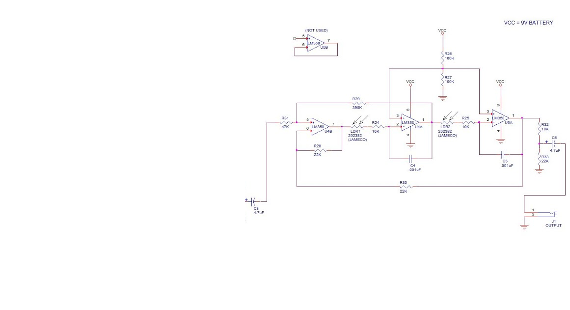
That's a variable state filter. It's a great sounding and highly tweakable filter.

I recommend making a few changes to improve it (not the layout, but the circuit) :)

1. Make an input buffer of the unused op amp stage. This will make the filter behave more reliable.
2. Change the filter input to be inverting - Change R31 to 22K and move it to the negative input.
3. Last step will allow for a resonance control. Add a pot from the positive input (pin 5) of the first stage to vref. A B10K should work fine. You will probably need an resistor in series aswell to avoid oscillation.
4. Make a switch to select either bandpass output (op amp stage 2 output) or the lowpass output (current output)
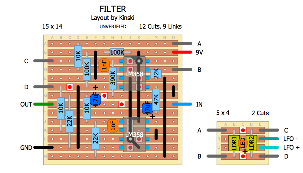
5. Add an LFO section to the layout to make it complete?

Just a few suggestions. I happen to recently have developed a DIY project around this filter, so this is fresh in my mind. I'm hoping to recieve and verify the prototype PCB by the end of the month. My design is a bit different and doesn't use LDR's.

Cheers / Fredrik
check out my building blog at www.parasitstudio.se
Reply | Threaded
Open this post in threaded view
|

Re: Awesome Filter!

Kinski
This post was updated on .
Wow, can't thank you guys enough for your input!

Here is an updated layout. I think I fixed all of the errors. I know the schematic show C3 opposite to how I have it, but on the youtube link, the guy mentions to flip this cap in using just the filter. So that's what I did. Input is supposed to go to - side.

Freppo, I'll read up more on your suggestions. But for now, I'm going to leave the filter as the schematic indicates and mod it if I'm unhappy.

I'm working on designing an insane keyboard/noise synth thing. A completely gutted early 90's keyboard stuffed with lots of oscillators and 4040s, CVs, etc. I've been breadboarding all my ideas and its working out really well so far. I've just been looking for the right filter. I haven't been completely happy with anything I've tried so far. This one caught my interest. I will have multiple LFOs on board to choose from. So I changed the layout so the LDRs are running to a small board with an LED. I'll then run the two leads off the LED to a switch that can switch in different LFOs.

For a fixed filter control, I was thinking of just connecting the LED to 9v with a small limiting and then a starve pot to control the brightness. In my head, I don't see why this would not work.

Anyone see anymore errors? I'm slow with these layouts, but learning all of the time, thanks to you guys!

/// UPDATED ///

Removed old layout.
Reply | Threaded
Open this post in threaded view
|

Re: Awesome Filter!

Ciaran Haslett
This one looks good too.

That LDR daughter board is a great idea.  Very elegant.  Great job lad
Reply | Threaded
Open this post in threaded view
|

Re: Awesome Filter!

Kinski
Thanks everyone!

I removed the old layouts above. Here is the updated one with component values and slightly smaller:

Reply | Threaded
Open this post in threaded view
|

Re: Awesome Filter!

ryder17
This looks great!

One question..... How come 2 ldrs are needed? Is it controlling cutoff and resonance at the same time? How can they be replaced by pots? Cheers
Reply | Threaded
Open this post in threaded view
|

Re: Awesome Filter!

Freppo
ryder17 wrote
This looks great!

One question..... How come 2 ldrs are needed? Is it controlling cutoff and resonance at the same time? How can they be replaced by pots? Cheers
Both resistors sets the cutoff frequency and needs to always be the same value, so you can use a dual pot.
check out my building blog at www.parasitstudio.se
Reply | Threaded
Open this post in threaded view
|

Re: Awesome Filter!

Freppo
In reply to this post by Kinski
I have just released a DIY project based around the same type of filter. :)

More info and demo video in this thread.

With almost 40 resistors and 14 op amp stages I won't even try making a vero layout for it, but if someone is feeling brave there's a schematic in the build doc. :)

cheers
/ Fredrik
check out my building blog at www.parasitstudio.se