Baby-8 Sequencer/LED driver

classic Classic list List threaded Threaded
21 messages Options
12
Reply | Threaded
Open this post in threaded view
|

Baby-8 Sequencer/LED driver

Neil mcNasty
Since the subject of Tone God's Vanishing Point came up recently, I've decided to post my layout for the Baby-8 Sequencer that I mentioned in that discussion.
This is pretty much the same circuit as the Vanishing Point, but with a simpler LFO/Clock based on the 555 timer IC.
I'm about to try this as a LED driver for an optocoupler, and then hook it up as a replacement for the LFO section in various modulation effects, like the MagnaVibe, Kay Tremolo and some Wah circuits, selectable via a Rotary Switch.
If succesful, I will do a report on that build when it is finished.

Note the layout does not have all step configurations possible, as I made it to suit my lovely russian millitary rotary switches. But it is easy to modify that, just pay attention to the pattern going on regarding the switch wiring, and you'll be able to customize it for your own use...

The layout has been built and verified!
Enjoy!

Reply | Threaded
Open this post in threaded view
|

Re: Baby-8 Sequencer/LED driver

notnews
This is great! I would love a build document in the vein of Madbean's build documents, something that explains what's happening in the circuit and how to exploit it and integrate what this circuit does into other circuits. Thank you for all your contributions here, seriously.
Reply | Threaded
Open this post in threaded view
|

Re: Baby-8 Sequencer/LED driver

skeletonghost
Amazing! The breakout board for the diodes is extremely useful!! I had the same idea after building my first sequencer. I wired the diodes directly to the pots and it was messy and difficult.
Reply | Threaded
Open this post in threaded view
|

Re: Baby-8 Sequencer/LED driver

Neil mcNasty
This post was updated on .
In reply to this post by notnews
Let's see if I can manage to explain a bit about it, based on what I understand...

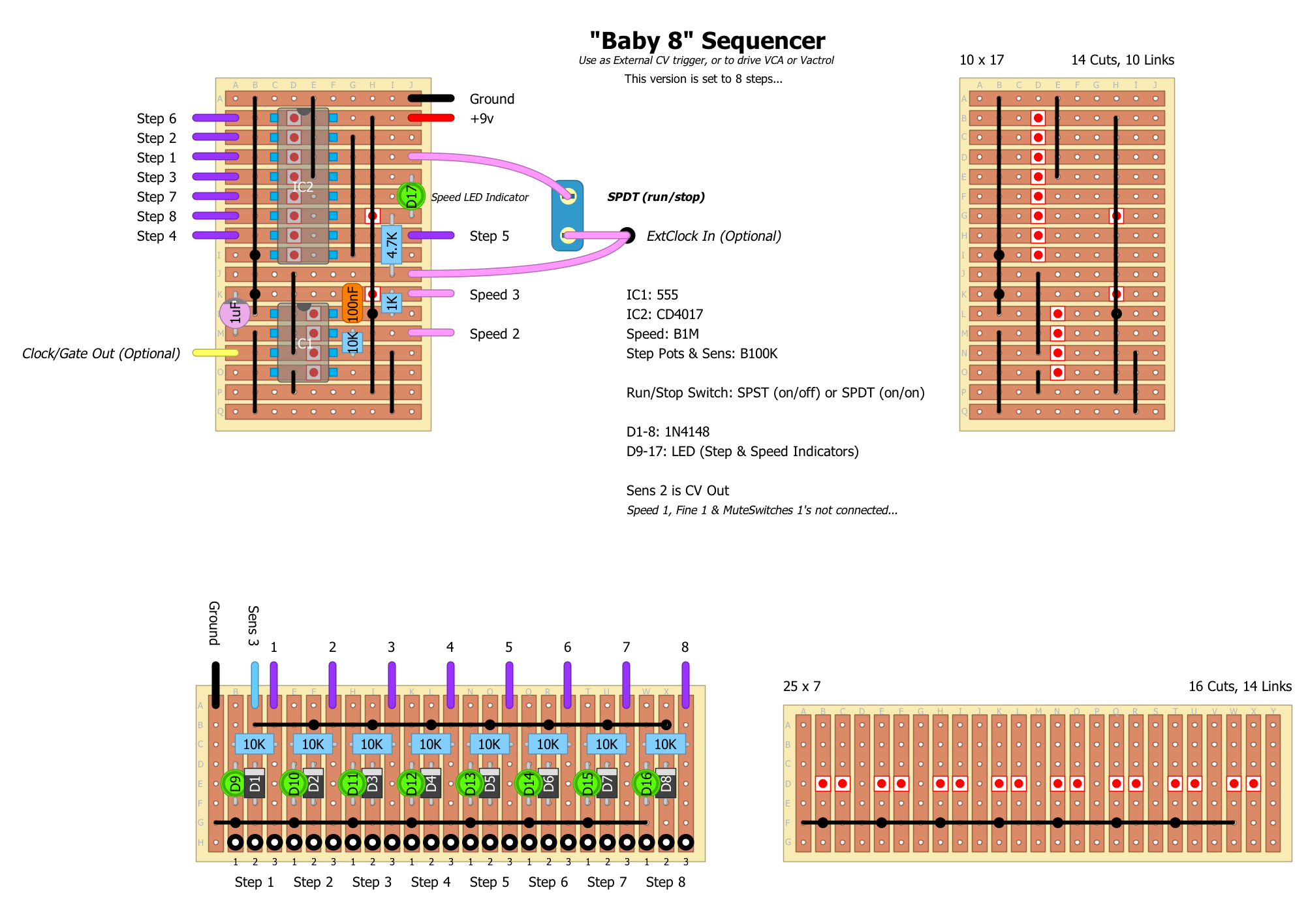
The main section and at the heart of this Sequencer is the CD4017 LED Driver IC
This is simply put, a 10 channel LED driver that ticks chronologically trough and activate 10 different LED outputs one by one, when receiving a short +voltage pulse to it's trigger input.
It is used in LED clocks to change to the next number, as the seconds tick by...
This is achieved by sending a pulse to the trigger of the 4017, which has it's 10 different outputs connected to a numerical LED.
This Numerical LED has separate lugs for each of the number to be displayed and a common ground, therefore this 10-step IC design. A 0-9 counter...

In this case, the trigger-pulse to drive the steps/outputs of the 4017 in sequences, is generated by the 555 timer, which function as a clock/CV pulse generator, with variable speed capability by changing the frequency of the pulse. The frequency is set by variable resistance via the Speed pot.

Think of this Speed pot as the Speed control for your tremolo!

The RUN/STOP switch simply cuts this signal coming from the 555, so that when the 4017 does not get any new trigger signal (stop position), so it simply stops. It will then continue to the next step in the sequence, where it left off, when the clock signal is returned (run position).
Sending a voltage signal to the re-trig input (actually called "reset"), at the same time as reactivating the clock signal from the 555, will start the sequence from step 1.

All the Step-outputs has their own Step-Sens pot and they all sum up via the (master) Sens pot, resulting in a single voltage output that has a 8-step adjustable pulse pattern with a master Sens pot at it's CV output.

Think of the (master) Sens pot as the Depth control of your Tremolo!

The Step-Sens pots can just as well be 8 compact on/off swithes for simplicity... This will save up a lot of space regarding housing/boxing it...


So far:
So what we now have here, is a very cool programable rhythmical voltage (or Ground) swing that can be put creatively to use.
Specially when we are dealing with circuits that has a LFO driven optocoupler involved.
And this unit now enables us to send out either a positive voltage swing, or a to pull a signal to ground.

We have multiple steps in sequence...
We have control of the tempo of the sequence...
We have control over the depth/sensitivity of each single step in the sequence...
We have a master control to set the Sens/Depth of the Sequence as a whole.
Cool!

Selecting number of steps:
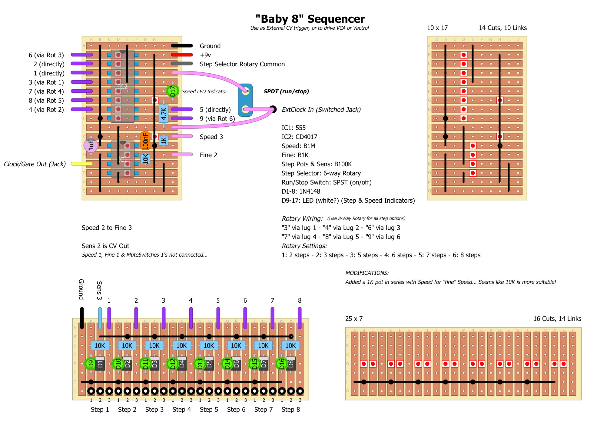
The number of steps can be selected, by connecting "the next number/output/step in the sequence" coming from the 4017, to it's own re-trig input. (the re-trig input is the grey wire that is labeled: "Step Selector Rotary Common" on my layout)

This means that, if you want a 4 step sequence... you then connect the 5th step of the sequence to the re-trig input, as this re-triggers the sequence, and then makes this 5th step, the very first step in the re-triggered sequence. Resulting in a 4-step continuos loop.

So therefore.... by (also) connecting the different/desired sequence step outputs to a switch (I used a rotary switch for this) with it's common going to the re-trig input.
You can then use this switch to set the desired amount of steps in the sequence, by sending the "next numbered step/output" compared to the desired number of steps you want, to the re-trig input of the CD4017.
So... Want 4 steps? connect step 5's output to the re-trig
Want 7 steps? connect step 8's output to the re-trig
See the pattern going...? use the next number in the sequence to set the desired number of steps that you want.

Adding a switch here, is a modification that I did to the Baby-8, in order to free it from being locked down as just a 8-step sequencer.
Now it can do a 1-step pulse, or up to a 10-step sequence. Each with it's own seperate Sens/Depth pot (or on/off switch) in addition to the Main Sens/Depth pot.
Making it useful for both extremely fast ringmodish 1-step tremolo stuff, ...to a mellow 9-step and complex wah pattern, all depending on what you hook it up to.


Synch and Chaos:
By having the "Ext Clock In" option that I added on the layout, it is then possible to take a clock signal from an external unit, and feed it to the "Ext Clock In" of the Baby-8, thereby bypassing the 555 clock/timer.

A "Random" mode can be achieved/added to the circuit, by sending continuous voltage to the re-trig input, this seems to confuse it, and make it sputter out pulses very fast and sputtery.
I'm considering running a wire from the +9v DC input to a 2 pole momentary stomp switch (normally off) and to the re-trig input


So...
How to use and implement it with other stuff?

I do not know all ways to use this, but here is how I look at it:

The output from the Sens pot is your LED-driving pulse. You can also look at it as a CV signal (a control voltage that can be used with analog synths that has CV-inputs, Gate-Inputs and similar), cause that's what it actually is... (has a range from 0v to about 6v if I remember correctly)

Since this unit is a sequencer that puts out voltage, we then have something that we can call an Sequenced LFO to drive an LED/Optocoupler, meaning that it can be used to replace the LFO in many circuits.
In this layout, it basically hooks up where the LFO signal hits the + side of the LED of the chosen effect's Optocoupler.
If you add a optocoupler at the end of this signal, you can then get variable resistance coming out at the other end, instead av a voltage swing. Meaning: you have a swinging Ground signal instead. And that is what is used to make a tremolo; it simply pulls the signal to ground/turns down the volume in pulses.


So that gives me a couple of ways to use this Sequencer:

One is to send voltages in patterns, as a LED driver, and
One is to pull signals to ground in patterns
I can also send and receive clock/tempo signals

By adding a Octocoupler to a Wah circuit (instead of the treadle-pot) you will have something in the style  of a SeekWah.
Replace the Wah with a Tremolo circuit, you have something like the SeekTrem.
How about hooking it up to a Phaser or a Univibe style circuit?
Chorus?
Reverb and Delay modulation?

CV and Clock potentials:
This kind of sequenced LFO can also be a very nice tool that can enable you to merge your guitar effects and their control parameters, with your analog synth rig, your drum-machines and sequencers, since these units often can send and receive both CV signals and clocks between each other.

- You can then, as an example; send a CV output signal from your pedalboard to the synth and apply the same pattern to the modulation of the synth's sounds as the one you have going on your 7-step'd psychedelic auto wah from your pedalboard.
- Or you can get a clock pulse from the main sequencer/pro-tools rig, and have your sequence in synch with the main-sequencer, at all times. The need for tempo adjustments between songs can be replaced with a clock signal, either if it is coming from an old unit with a CV/Clock output, or via a jack from the sound-card of a DAW.

I see many potential uses for this circuit, and the idea of building many (LFO-free) modulation effects in  rack units, and then add units with this sequencer + different LFO's that can be patched to these different modulation effects,...
Well... It starts to intrigue me!
Specially for the recording studio!
An old style modular synth approach to guitar modulation effects, with endless patchability....


I hope this helps you to understanding this kind of circuit, at least it is an attempt to describe how I see it...

If someone now could crack the code on how to get a tap tempo control added to it without a shitload of circuitry, then the possibilities would become very interesting...
A very simplified Taptation replacing the 555 maybe...?
Definitely something worth considering...

Cheers!
Reply | Threaded
Open this post in threaded view
|

Re: Baby-8 Sequencer/LED driver

Hozy31
In reply to this post by Neil mcNasty
Hey Neil,

Thanks for the explanation. This looks awesome. Really looking forward to what you manage to achieve. These are the sort of projects i am really interested in. If you need help in veryifying any ideas let me know. I am a rather obsessed builder.
"Red velvet lines the black box"
Reply | Threaded
Open this post in threaded view
|

Re: Baby-8 Sequencer/LED driver

Dadio
 I think I bit off more than I could chew. Any guidance would be much appreciated.

I tried to use this layout to make a simple four step sequencer for an Atari punk console for my son.

Here's what I did:

I made the diode board half the size by eliminating the middle 4 steps.
I eliminated the rotary switch by connecting 5 (pin 10) to reset (pin 15)
I connected 1-4 to the diode board and left 6-9 unconnected.
I eliminated the run/stop switch.
I eliminated the fine pot by connecting speed 2 to fine 2.
I eliminated the clock/gate out.
I connected the sens 3 and ground from the diode board to a jack.
I connected pin 5 on the ic1 (555) on the APC (Paul in the lab layout that uses 2 -555) to a jack and
connected the two jacks.

Here's what's happening (or not happening):

no sound
the led s on the diode board are not lighting
the speed led is lighting and blinks faintly and does change its rate when adjusted.

I cannot find any bridges or shorts but I don't know if the changes I made if I should even expect it to work : )

I had joined this forum last year under the name gravedancer but I couldn't login with that name as I forgot what email address I used and couldn't have the password sent to me , which i also forgot lol.
Getting old is a drag, but I guess it beats the alternative : )

If Neil or someone could give me a little guidance I'd really appreciate it. I've built a few pedals thanks to this site and the kind folks here but am still definitely a beginner.


Reply | Threaded
Open this post in threaded view
|

Re: Baby-8 Sequencer/LED driver

Neil mcNasty
My build works perfectly ok, so I suspect an error in your build.

Important:
The ground connection on the breakout-board must connect to "proper" Ground, or else it will not work...
If you have your Jack "floating" (not mounted to a grounded chassie), then that part of the curcuit is not grounded and will not work.
Give me a sec and I'll post a cleaned up version that is identical to the schematic, so that it is easier to bug-test...
The one I posted is a bit messy because my own tweaks.
Reply | Threaded
Open this post in threaded view
|

Re: Baby-8 Sequencer/LED driver

Neil mcNasty
Here is a cleaned up version that matches the original schematic.

Reply | Threaded
Open this post in threaded view
|

Re: Baby-8 Sequencer/LED driver

Neil mcNasty
...and here is the layout that I copied (for reference)
Link: http://electro-music.com/forum/phpbb-files/thumbs/t_baby_sequencer_v1_128.jpg

Reply | Threaded
Open this post in threaded view
|

Re: Baby-8 Sequencer/LED driver

Neil mcNasty
By the way... Have you seen this?
http://www.owyheesound.com/img/atari_punk_console.png
Reply | Threaded
Open this post in threaded view
|

Re: Baby-8 Sequencer/LED driver

Dadio
In reply to this post by Neil mcNasty
Hi Neil   Thanks for responding. I had no doubt the layout was correct . I was concerned with the changes I made as to whether they were correct as to making sense electronically (does that make sense?lol)
My grasp of electronics at this point is elementary at best.

I also forgot to mention I used 20k pots as that's all I had on hand. I didn't know if that mattered or not.
Although i've read some on it I'm still not sure when pot size matters and when it doesn't.
This may be a dumb question but if the circuit is unboxed/floating where do I connect the ground.

Yes I saw that diagram and it was helpful as far as getting my head around the connection between the atp and seq.
What I was trying to do was the simplest bare minimum 4 step sequencer I could.
It must be frustrating to answer questions  like mine .I really do appreciate it.


Reply | Threaded
Open this post in threaded view
|

Re: Baby-8 Sequencer/LED driver

Neil mcNasty
No frustration in answering your questions mate!
This place is all about the joy of helping out and sharing knowledge, and it is an honour to be able to reach a point where I am also able to help out.
Most of the stuff I have learned about this has come from people on this forum, and it is amazing to see how many people have grown in their knowledge simply by asking questions.

As far as I can tell, your changes does not have any obvious mistakes that I can spot, except for the ground connection to the breakout board.
The breakout board's ground should connect to a ground point on the main board, or directly to the DC Jacks ground.

In this case a 20K pot will probably be too low, as it will only pass 20% of the power to the LEDs, compared to a 100K pot, and therefore it might be just below the value where it starts to light up...

In most cases the pot value does indeed have an impact on how the circuit behaves, so therefore I find that it is often better to use a pot that is a bit too big, instead of one that is too low.
You can then (if you like) add a resistor between lug 1 and 3 of a larger pot to bring the value down. (this changes the Taper response a bit, but not drastically)
If doing so, you must calculate the final value the same way as; when putting two resistors in parallel in order to create the new value.
Example: two 100K resistors in parallel, makes 50K.
Two identical resistors are easy, since it makes half the value..
The tricky part is to calculate the result with resistors of different values, so I recommend that you download a electronics calculator/converter app for your smart-device that can calculate parallel resistance.
These are very handy when dealing with these kind of issues...
Reply | Threaded
Open this post in threaded view
|

Re: Baby-8 Sequencer/LED driver

Dadio
Thanks for the positive thoughts and attitude. One of the many reasons I like this site .The folks are truly friendly ,an internet rarity.I've been lurking for a couple years. I don't post much because I have (at times extreme) social anxiety issues.One would think the anonymity of the web would lessen this but it doesn't.

I have 100k pots on the way so I'll switch them as asap and see where that takes me and Thanks for the pot info. Iv'e read things like that before but it clicks better when someone is explaining it directly for me.

I'll update my progress when it happens .
Thanks again!
Reply | Threaded
Open this post in threaded view
|

Re: Baby-8 Sequencer/LED driver

WeStartToDrift
In reply to this post by Neil mcNasty
I built this the other day. I strongly recommend adding a 100uF cap between +V and Ground as the 4017 was misfiring like crazy without it. With the filter cap it works perfectly. Thanks for the layout.
Reply | Threaded
Open this post in threaded view
|

Re: Baby-8 Sequencer/LED driver

kuzieem
In reply to this post by Neil mcNasty
Where does "9 (via rot6)" go? There are only 8 slots on the other board...
Reply | Threaded
Open this post in threaded view
|

Re: Baby-8 Sequencer/LED driver

Neil mcNasty
Ignore the word "via".
It goes to the switch, nothing else/more...
It is a slight error on my behalf.

"9" is the "9th step" that triggers the sequence from the start again, so that "step 9" actually becomes the first step, after re-triggering the sequence. Does that make any sense...?
(I think there is a better explanation in one of my long posts above, if my words are too cloud...)
Reply | Threaded
Open this post in threaded view
|

Re: Baby-8 Sequencer/LED driver

kuzieem
So 9 goes to the switch pin 1? Just to make sure...
Reply | Threaded
Open this post in threaded view
|

Re: Baby-8 Sequencer/LED driver

Neil mcNasty
No!
Switch pin 6 ...as it is labeled.
You should only ignore the word "via"
(because it only goes to the switch, and nothing else! The word "via" snuck in and should not be there, meaning; it should have been labeled "Rot 6" and not "via Rot 6"
Reply | Threaded
Open this post in threaded view
|

Re: Baby-8 Sequencer/LED driver

kuzieem
Many thanks!

One more question:
The bottom board is described as 14 links but I've found 15. Also, one view is 25x7 whilst the other next to it has 25x8 Are those the same?
Thank you.

01.11.2017 20:08 "Neil mcNasty [via Guitar FX Layouts]" <[hidden email]> napisaƂ(a):
No!
Switch pin 6 ...as it is labeled.
You should only ignore the word "via"
(because it only goes to the switch, and nothing else! The word "via" snuck in and should not be there, meaning; it should have been labeled "Rot 6" and not "via Rot 6"


If you reply to this email, your message will be added to the discussion below:
http://guitar-fx-layouts.42897.x6.nabble.com/Baby-8-Sequencer-LED-driver-tp26665p40378.html
To unsubscribe from Baby-8 Sequencer/LED driver, click here.
NAML
Reply | Threaded
Open this post in threaded view
|

Re: Baby-8 Sequencer/LED driver

grayfox13
In reply to this post by Neil mcNasty
Dear Neil, i was wondering how to use this sequencer, that i've already build, to drive a ring modulation as in the ZVEZ effect ring modulator (see video)
https://www.youtube.com/watch?v=_B0bcXuKjW4

The modulator has exactly the same controls but it use the sequencer to drive the pitch of the ring modulation and then mixing it back.

Any ideas on how to implement it for a stompbox guitar pedal? :)
best regards
Luca
12