Benson germanium fuzz - schematic to vero?

classic Classic list List threaded Threaded
7 messages Options
Reply | Threaded
Open this post in threaded view
|

Benson germanium fuzz - schematic to vero?

tomeunknown
Hey peeps .. anyone interested in transferring this onto a vero layout? (From a thread over at FSB)

Reply | Threaded
Open this post in threaded view
|

Re: Benson germanium fuzz - schematic to vero?

Axldeziak
This post was updated on .
Here are two layouts I did for the input buffer/pickup simulator, as well as the power inverter/heater. This way any premade germanium Fuzz Face layout could be modified to be used with them.


Reply | Threaded
Open this post in threaded view
|

Re: Benson germanium fuzz - schematic to vero?

Silver Blues
Wow this is a really clever idea. Nice.
Through all the worry and pain we move on
Reply | Threaded
Open this post in threaded view
|

Re: Benson germanium fuzz - schematic to vero?

gennyespo85
In reply to this post by tomeunknown
hello and congratulations for the work done on this benson.I wanted to ask if this scheme was verified as I believe there is some error, i.e .:
1) the operational rc4558 pins 5,6,7 are not listed in the diagram
2) the cooling resistors of transistor 2n5191G in the diagram are listed as 68R 1 / 2W while in the image below you say they are 68k 1 / 2w (which are they really?).
3) under the 1k trimmer there is written 757R on the tested unit What does this mean?
4) There is no + 9v connection listed but only V + references, where do we start with a + 9v connection? it is assumed that a connection could be applied on the reference v + on the diode 1n400x ????
thank you for the answers you will give us
Reply | Threaded
Open this post in threaded view
|

Re: Benson germanium fuzz - schematic to vero?

Axldeziak
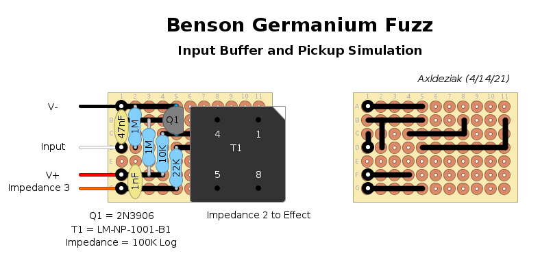
Thanks for spotting the error with the heater value. I corrected the layout posted above,

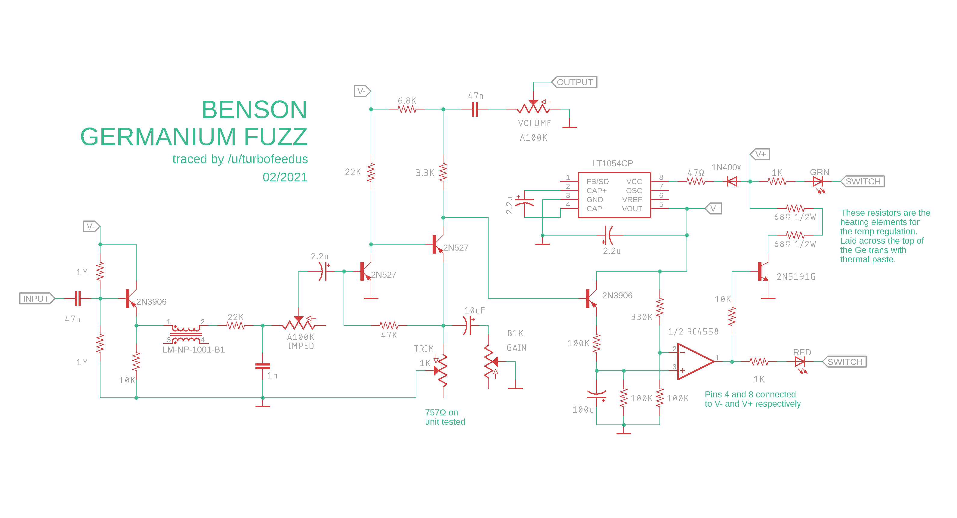
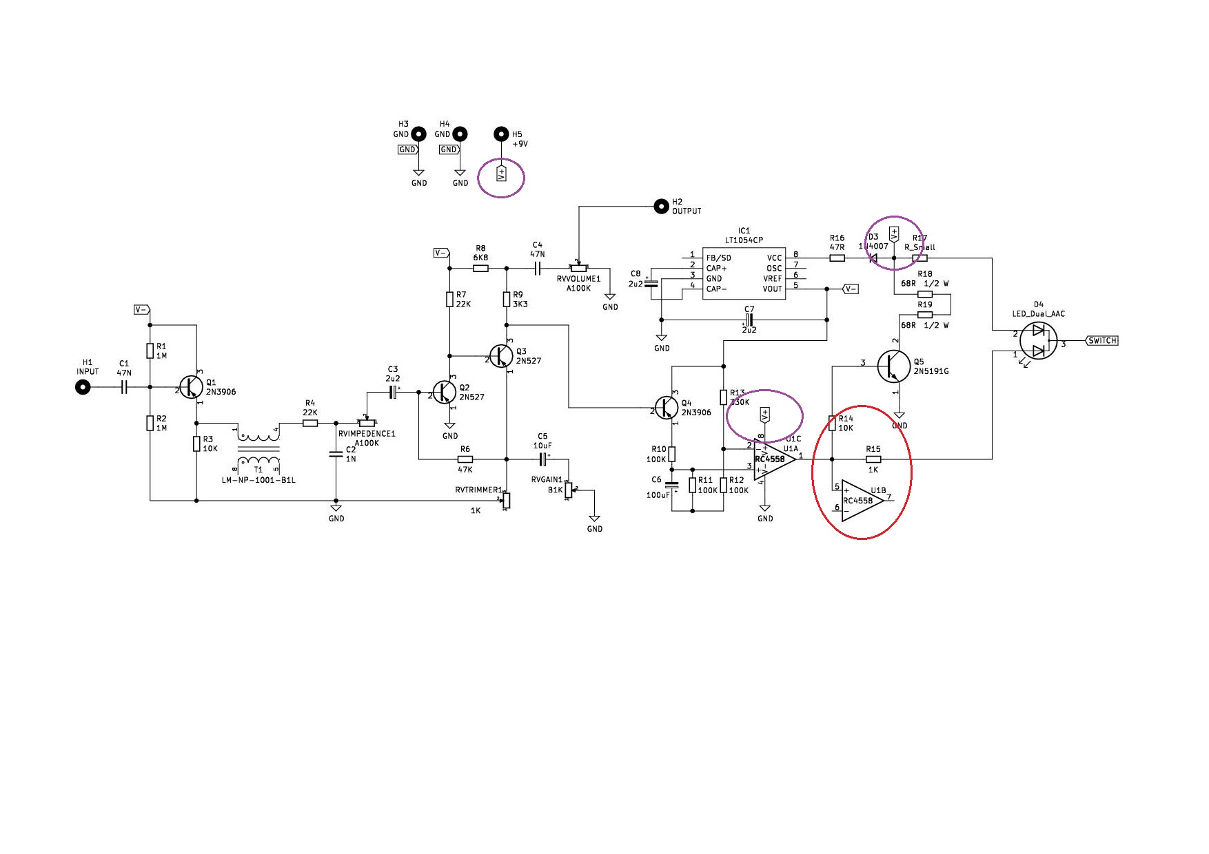
The 4558 is a dual opamp. The schematic lists 1/2 RC4558. That means only one op-amp of the dual package is used and as such the nonlisted pins where not used. My layout uses a TL071 as it's a single op-amp and the pinout is slightly different. Download and compare the two different datasheets and you will see the differences and similarities between the two.

757R means the trimmer was adjusted to 757Ω (ohms) resistance. The two symbols Ω and R are interchangeable and mean the same thing.

The +9V is the V+.
Reply | Threaded
Open this post in threaded view
|

Re: Benson germanium fuzz - schematic to vero?

gennyespo85
hello should this be the correct schematic? I circled the connections for the 9v in purple and the other part of the opamp pin 5/6/7 in red. as a scheme, and if you want you can also post it on the page.

Reply | Threaded
Open this post in threaded view
|

Re: Benson germanium fuzz - schematic to vero?

Axldeziak
If you insist on using a dual opamp, the proper way to terminate the unused side is to connect 6 and 7 together, and 5 to ground.