Best way to wire a 3PDT ?


|
Hi,
There is a lot of way to wire a board with 3PDT. Some say that it's better to put all the ground directly on the board (dc jack, input, output), some use the ring of the input jack for all the ground connection, or by the 3PDT, with only one ground connection on the board... So, all this ways works, but for have the less of noise and "interference" what the best way to wire a board with 3PDT (with true-bypass and led) ? if there are a best way ;) For example (just one example among many other), I build the Current lover flanger from Madbean (EHX Mistress clone), and that's how he cable the 3PDT : DC ground on the input sleeve, then the 3PDT, and only one ground on the board, no ground connection on the output (grounding by the enclosure). http://www.madbeanpedals.com/projects/CurrentLover/CurrentLover.pdf Thanks |
|
|
This post was updated on .
The "best way" is the way that works. I am sure most people who have been doing this for awhile each do it the same way every time, but that many of them use a method that varies from other people.
Here is the actual link to the madbean pedal offboard layout: http://www.madbeanpedals.com/tutorials/downloads/StandardWiring_MBP.pdf and for me this was the best one for quite awhile. But here is a different one that also works fine: 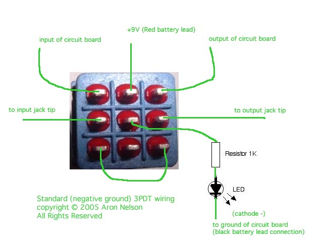 Then Beavis is also different:  Then I also noticed some people here use a different system where lug 3 is tied to 7. Not shown in any of the examples here. So, it just goes to show you there is no one way to do it. The best ones have a solid ground, and leads that go to the input tip on the left when building (so the input is standard right side when finished) and the output the left (when the pedal is right side up). Like in the pic above - the actual jack should be wired "backwards" input left/output right when upside down, so they are oriented correctly when turned over. Most of the best ones also use outside lugs (nearest the circuit) for the LED or the +9 - because the LED is usually placed just above the foot switch, and +9 voltage is critical. Some have the LED go to a CLR and then to the DC +9 jack. Some bring +9 to the foot switch and power the LED. Grounding is critical, and ideally should include a ground to everything (although I see madbean leaves it off the output) - but you need to ground the input, the DC jack, the effects board and the foot switch. Personally I also ground the output ring. A lot of people also recommend using metal jacks so you are also grounding the casing, where if you are having a hum is a good idea. I usually have a wire with alligator clips handy when building a circuit so I can quickly run a ground wire if I have to do it. Especially when you first out, but after a few builds you start to just know where all the grounding will go. Also - fitting everything into the enclosure is tricky, and the fewer wires you have to run under the effects board the better - so logically the DC jack should be close to the footswitch and in/out jacks for shorter and cleaner ground wires, but not always. A lot of pedal USERS prefer to have all jacks at the top so they can get their pedals closer together on a pedal board (a standard TGP consideration). It is harder to build them that way, but can be done with more of an "upside down" approach to layout. |
|
|
This post was updated on .
In reply to this post by Thelonious
I used to wire my switches manually, but now I simply use the Vick Audio 3PDT board. Easy to install and makes my off board wiring a snap. There's even a place for the LED + resistor.
 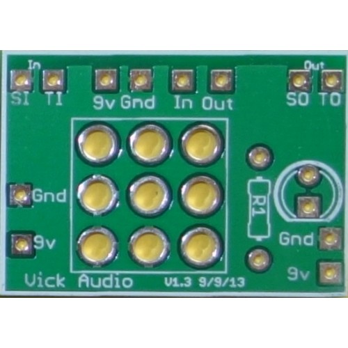 Check it out at the following link: Vick Audio |
|
Administrator
|
i have the 3PDT boards that stinger sells in the market section of the forum here. but when i do it manually i use the method mark has posted on the main site religiously and exclusivly, and if i want to add a battery snap its a quick simple add. i've never had a switch not work when i've followed it, but have had some of the other methods give me issues, which is why i follow the one here like i do. it never fails me, and at this point, after using it on over 100 pedals i know it like the back of my hand.
|
|
|
Thanks for all your answers.
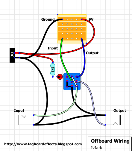
3 answers, 3 ways to wire a 3PDT ;) So, no silver bullet. Personally I don't like to not grounding the output (and use just the enclosure for that). And I prefer to put the DC ground directly on the board, not just by the input. I'll try the "Beavis" method, plus a connection between dc ground and board. Until now I used the method of Iviark (like rocket88), works very well, but with some effects (with a lot of transistor like fuzz) I have sometimes a noise "hum", and I have less noise, when I put all the ground on the board. |
|
|
I also got hum from the off-board posted here, but I think it was because I missed running the ground to the foot switch. His layout obviously works, and is clean. I also got hum with beavis at first. madbean was my cure.
I am now also using the stinger boards which do the trick. Once you get the basics down, though, I am not sure PCBs are that much faster. I did see one PCB board that also included holes for these:  in a standard 1590B enclosure. That seemed pretty handy to me. But I can't find them now. |
|
Administrator
|
Madbean's is exactly the same as mine but with the added battery snap. I used to do the conventional true bypass switching as per the Beavis diagram and the one with green text. I swore by it and used it religiously right up until the first time I got bleedthrough. Using the grounded input method sorted that out and I've never had an issue with it since.
|
|
|
This post was updated on .
Mark - I only looked because you brought it up. I think another difference is grounding the circuit - you go from the dc supply ground to the circuit, madbean goes dc supply ground to input to footswitch to circuit. You also tie input and output jacks together (as you said).
I actually think your design is more solid now because I know that having a "single line" of ground end to end is preferable to avoid loops, so at this point, while I now prefer your approach to madbeans, I think I just found his easier to understand at first, and it had to do with how I was making circuits at first - with no testbed and actually wiring in all inputs, pots, LEDS, battery adapter, DC adapters, etc. Once you get a test bed it all becomes much easier - especially when this site largely focuses on circuits only. One thing I have mentioned is my struggle with getting LEDs to work. I think one extra I got from Madbean is the LED anode and CLR are more clearly marked. MY problems are not your problems, however, so please don't take this personally. I know where I struggled, and I am just glad I am past it. For you, problems like mine are so old you probably don't even remember what it was like to have them. I do know that no matter what layout I referenced I always had alligator clips handy to make a ground contact and fix a bad hum. What I didn't (and still don't know) is what I was doing wrong, but I suspect the LED, and the ring on the DC jack (which I wanted to include but you don't use) are what kept taking me back to madbean. These are all just tricks you learn over time. It's all good, tho. This is just discussion my friend, not a critique. We noobs occupy a different universe. |
|
Administrator
|
dude, the madbeans method and marks ARE identical are are grounded the same way, and the ONLY difference is that madbeans adds a battery snap. because of that i don't understand how you could prefer one over the other if they are both the SAME. that's like if i gave you a cup filled with coke in a pepsi glass and you said you prefer the one in coke glass more.
 i know that the LED wiring has been your adversary, like Grendel to Beowulf, but i don't understand how it's causing that much trouble for you. in marks or the madbeans wiring layout, you have the power AND the LED anode connected to the same post on the DC jack. in between the wire from the cathode DC to the LED you have your resistor. the anode of the led is connected to the switch. it's that easy. as far as you're comments about grounding issues and hum, something you're doing is wrong. i would venture a guess and say that you're jacks aren't making good contact with the enclosure. are you painting them after drilling? are you using one that have been powder coated and drilled? if so, there could be paint or powder coat in the hole where the jacks go through, which would prevent them from grounding properly. in over 100 pedals i've built i have not had one that had a hum due to grounding, or lack there of. i even use the cheap-o tayda electronics jacks, which i love and fully support in place of expensive ones, i see it as a waste when the others are just as good, plus the black insulators look nice inside the enclosure. i have had high gain pedal or some old fuzzes that are noisy, but not a hum as you describe them. also, the hum could be produced by a cheap-o power adapter, which is usually the cause. |
|
Administrator
|
Yes grounding in the diagrams is just a typical representation. All grounds should be connected together, so how you prefer to do it, individual wires, daisy chains or whatever, the result is the same. A common ground.
If you're having problems with noise or anything else which you put down to grounding, make sure that every point of ground is connected and so you have no resistance between them. The board, socket sleeves, DC adapter, pots, etc etc. If they aren't then your build isn't properly grounded and you need to work out what connections you've missed. |
|
|
In reply to this post by rocket88
"as far as you're comments about grounding issues and hum, something you're doing is wrong. I don't understand how it's causing that much trouble for you"
I just want to clarify a couple of things. (1) I did resolve my grounding and LED issues quite awhile ago, actually - so thank you, so if I refer to them it is about what happened in the past, and I only share to help other people who are having the same problems I had. (2), I thought I was pretty clear when comparing these two offboard schemes that I was solely referring to the order of physical connections - which is really all that counts in this conversation - because as you correctly stated, they are "identical" - in theory. As someone said - electrons move really fast so the order of components doesn't matter. But in the physical world these two layouts are not identical at all. And that was all my post was addressing. Does it matter? Not to you - but it does to the person who started this thread, because they don't know the "theory" you are referring to... they are trying to learn by doing. Here is a good example of where one can go wrong with grounding - The DC jack ring is not shown here. When I started I tried using this offboard guide, but I think I confused the DC ring for ground a few times. Then I would get a super loud hum in my amp that had my wife shouting from the other room when I turned my effect on. See, it isn't a matter of what you read or see when you start researching this stuff, it is a matter of what your mind retains when you start DOING this stuff. Nothing teaches like experience and repetition. Of course, when you make a mistake like that you don't know what's wrong until you figure it out. Hence, noobies, don't know what they don't know. The way people read posts varies depending on their experience level - and how they perceive the post writer. I am getting much better at all of this. I could almost pretend I never made a mistake, but not quite - plus that would be a lie. Mark - you seem to understand where I am coming from, so I thank you very much for your patience. And Rocket, you have also been helpful to me. I think I just need to clarify that I am getting it much more now, so if you read my comments from that perspective I think they make more sense. |
|
Administrator
|
i'm sorry, but you make 0 sense to me. the layout mark posted and the layout from madbeans are identical in theory and in the physical world, unless you operate in a completely different world then me. the wires all go to the exact same places, and are shown to be going to the exact same places on each.
the dc ring is shown in marks layout, you can see it as a black wire, as black is universal in electronics for ground and red is universal for positive, which are both marked as ground and 9V respectively. that is electronics 101. if i say anything else i have the feeling it's going to get nasty, and i'm going to be rude, so this is the last i'm going to comment about the wiring. i want no drama.... |
«
Return to Open Chat
|
1 view|%1 views
| Free forum by Nabble | Edit this page |