Booster Idea and Help


Administrator
|
So I have this crazy idea of trying to build a one knob booster, with two transistors (one JFET, one germanium), for bass. I got the idea while looking at the vero for the AMZ Mini-Booster, cause I know it's fairly clean sounding, but I want to get a little bit of germanium grit, warmth, and color to the output. I think it will go really nicely with my playing style. I have a few questions. One, how can I tell which is the first and second gain stage. Second, is how can I replace one of the gain stages with a germanium transistor. Third, would it be better to try to modify the circuit with germanium clipping diodes. If so, how? Lastly, with a lot of pedals made for guitar, what is a good way to tweak them for the low frequencies of basses.
I've been messing around with a lot of the pedals here and making my own variations for guitars with good results, and would love to have a good jumping off point so my basses don't feel left out. THanks for any help in advance guys. |
|
|
The first gain stage comes first, I don't think I understand your question. Your 2nd I can't help with. If you add clipping diodes then you are essentially going from a booster to an overdrive pedal, it certainly won't be clean anymore. You could always go for a diode lift switch that'd allow you to toggle the diodes in and out of the circuit. Your last question, generally a good first thing to look at is your input and output caps, making them bigger will allow more bass frequencies in and out of the circuit.
Hope that is useful in some way. Thanks Dave |
|
|
In reply to this post by rocket88
The Mini-Booster only has one gain stage. The two jfets are used in a kind of push-pull arrangement, where they both contribute to the single gain stage.
In any case, the AMZ G-spot substitutes a Ge tranny for the lower jfet to achieve what I think you're asking for. Unfortunately, I can't find a schem, but you can experiment. Here's a gut shot, that might give you some hints. 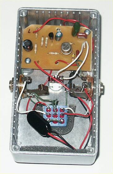 Jack Orman says that subbing the upper jfet with germanium won't add much flavor. Read more here. Another option is to slap a simple ge gain stage in front of a stock minibooster. Google 'amz brown sound' for more details (he uses a pnp ge common emitter that's compatible with negative ground power supplies). Dave is correct, if you add clipping diodes, it won't be much of a booster anymore. The diodes clip any signal larger than their forward voltage. For ge diodes, Vf is about 0.3V, so your maximum signal would be 0.6V peak to peak if you put them at the output. You could add another boosting stage afterward, if you want to go that route, but it will probably get noisy fast since the diodes attenuate the signal, but leave the noise intact. Dave is also correct about swapping input and output caps to tailor the frequency response of a given pedal. Another way is to make your gain stages frequency-dependent. For example, reducing the emitter resistor in a common emitter amplifier increases gain. If you parallel that resistor with a capacitor, you will increase gain for high frequencies, but not for low frequencies. The frequency-dependent gain can be calculated with the gain formula, the equation for capacitive reactance, and the formula for adding resistors in parallel. Similar tricks can be used for other types of gain stages, and for boosting bass instead of treble. Which strategy you use depends on what you want to accomplish and which circuit you're adapting. For example, frequency shaping before distortion has a much different effect than similar shaping after distortion. Noise can be a consideration, too. The breadboard is your friend for stuff like this. Hope this helps. |
|
Administrator
|
Thanks guys. Dave, I understand the first gain stage always comes first in the circuit and can figure it out on non-vero circuit boards. What I was trying to ask is when looking at a vero how can I tell the first gain stage from the second. For instance if you look at the creepyfingers fuzz, here, aren't there 2 gain stages? I found something that kind of explains what I was thinking. It's from Wren and Cuff its the phat phuk b, video. I get why adding the diodes makes it more of an overdrive, which is why I was thinking that using a transistor would just add that sound I was thinking. Induction, this is a noob question, but if I added a gain stage before or after the booster, or added any stages to an existing circuit how can I do it on the same board?
Thanks guys for the help so far, and I'm going to actually get a breadboard and finally learn how to use it. It's always confused the hell out of me, but it's time to learn it. |
|
|
"...when looking at a vero how can I tell the first gain stage from the second."
My advice, never use a layout to examine a circuit. Get a schematic instead, that's what they're for. (Search google, fsb, diysb, etc. Check out the links at the bottom right edge of this page.) If you have the layout and you can't find a schematic, use the layout to make your own schematic (it's both useful and good for you). So the answer to your question is 'compare the layout to the schematic until you know what each component corresponds to.' For example, looking at the mini booster schematic, it's obvious there is only one gain stage. Figuring that out by looking at a layout is not a simple proposition. In fact, I would never even build a circuit from a layout without having a copy of the schematic (though nowadays I make all my own layouts) because debugging is too hard without one. As far as adding a gain stage, you can either put it on a separate board or you can make a new layout that incorporates the whole circuit. I'm glad you're going to get a breadboard. Once you get to the stage where you are modifying circuits or designing your own, you really can't do without one. I breadboard everything before I build it, even if I'm not planning on modifying it. Sometimes I just want to see what a circuit sounds like before I decide whether to build it. If you plan to swap input caps or make some other mods, you'll want to know how it sounds before you commit. Most simple circuits can be breadboarded in minutes. That Wren and Cuff pedal sounds like maybe a jfet buffer feeding a germanium common emitter amplifier, or some variation on that. Slap something like that on the breadboard and see how it sounds. Swap components and rearrange stuff until you get something you like. It's the best way to learn what each component does, and very often you'll end up with something cool that you weren't even looking for. I also recommend looking into diylc. It's free software for designing your own layout (vero, perf, even schematics). It is very handy and easy to use. Designing veros is easier than it sounds and gets even easier with practice. If you're going to design your own circuits, you really can't beat it. |
|
Administrator
|
Cool. Thanks Induction. You've been a huge help so far. I just got DIYLC and going to work on it a bit. If I try what you say and put two circuits on one board, I have to make sure the input of one is connected to the output of the other, and I have to make sure they share power and ground right? Also, if I try and add a gain stage, how can I place it in the same circuit? I want to actually have this controlled by a single volume knob. So the first stage drives the second. Still very new to vero designing, and love it over making my own circuit boards like I used to.
|
|
|
You got it. Plug the output of the first stage into the input of the second. The first stage will usually have an output cap, and the second stage will have an input cap. You only need to keep one. I'd probably ditch the input cap of the second stage and keep the output cap from the first, but you can experiment.
As you said, they should share power and ground. No need to duplicate power filtering polarity protection. If they both have a Vref that's the same, you can usually share that too. You have lots of options for volume knobs, so you'll have to experiment for any given pair of circuits. Some volume knobs come up front and limit the amount of signal getting into the circuit, others come at the end and limit how much signal gets out. Yet others control a gain stage. They may behave differently depending on the circuit. For example, pre-gain volume reduction will reduce clipping, post-gain volume reduction reduces volume after the clipping has occurred. Reducing the gain of a gain stage can have various effects depending on the circuit in question. Look at the volume control in your circuits and figure out what they control and what results you want, then breadboard all the interesting combinations. Eg, if you want the tone to be the same at all volumes you might want only an output control; if you want distortion to increase with volume you might want only an input control. If you decide to ditch an input or output volume knob, you can replace it with a trimmer of the same value or a voltage divider with values that replicate your favorite setting. If you replace a variable resistor in a gain stage, you can replace it with a trimmer or a fixed resistor of the value that replicates your favorite setting. If the first circuit has an output control and the second has an input control, ditch either one. If the first has no output control and the second has no input control, you can always add a control between them if you want one, or add a fixed voltage divider to reduce the volume before the second circuit, if necessary. On boosters that color the tone, I usually add an output control so I can get the tone I want independent of volume. I've barely scratched the surface here. You'll have to use the breadboard and your imagination to see what you like best. Good luck. |
|
Administrator
|
Thanks induction. I'm away till tomorrow, but will be getting started as soon as I get home. I still have a few questions. First if I'm taking multiple circuits and combining them on one board do I want to to just make one circuit then separate them by making a barrier by making a line of cuts and just run a jumper for power and ground to connect the circuits? Second, if I remove the volume lot from the first circuit, which had the output, how do add a resistor or trimmer so that I can connect it to the second circuit? I don't want to have a daughterboard, so should I just make an additional column? What if I want to keep the volume of the first circuit and remove the second, wouldnt that mean I would have a pot connected in the center of the board? Also, I'm thinking this is a booster/overdrive, if I wanted to do this as 2 different stages how do I add the addional stages as powered stages? I think I read on Beavis or muzique how to add a tone control to any circuit, but it's passive and I wouldn't want to lose output. I guess I'm asking more how to add an additional stage whether gain stage, tone stage, or other to a vero circuit?
I've read over marks layout guide and I really have trouble understanding how to know where each component goes so that the pots are on the ends of the board. Im still having trouble placing components so everything works right, and is near and clean. |
|
|
The answer to most of your questions depends very much on the specific circuits you are combining. There is no single answer that works in all cases, except to draw a schematic of the entire circuit you want to build (ie both subcircuits in one diagram) and then create a layout for that schematic from scratch.
If you want to adapt existing veros, it's often easier to make them separately and attach them with wires. Otherwise you may end up with connections in the center of the board (which not necessarily bad, by the way). If you don't want all connections on the edge of the board and you only want one board, then you might be able to stack the layouts instead of running them side-by-side with cuts between them: 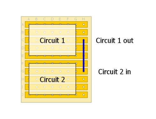 You may have to add some columns to make all of the necessary links for power, etc. If the first circuit's output is on the opposite side of the board of the second circuit's input, and you don't want a volume control to connect them, you can just rotate one of the boards 180 degrees. Absolute orientation doesn't matter so much. Remember, if you choose to ditch an input or output volume control (these are usually set up as a voltage divider with three connections), you will need two resistors, not just one, unless you want the volume all the way up. As far as tone controls, you are correct, many of them are lossy. If you lose too much volume you could add a gain stage before or after. I like to add it before because the gain stage will introduce noise and the tone stage will drop the noise, but then you'll often want to add a buffer so that the output impedance doesn't depend on the tone settings. You'll also have to beware of clipping (you're more likely to clip when you boost a signal and let it drop than when you let it drop and boost it back up). So better performance, but extra complexity and more components. (On the other hand, TL072 cost roughly the same as TL071, and take up the same space.) If the gain stage doesn't add too much noise, then putting it after might be better. Also beware that many some tone stacks have massive volume variation depending on the settings (standard Fender tone stacks, for example), so you'll have to breadboard or sim them (download LTSpice IV) to see if you can live with that amount of variation, unless you're willing to add another volume control to the booster stage. As you can see, we're always dealing in trade-offs. Generally so many of them that there are no hard and fast solutions that I can hand you, or even lay out all of the options for every possible scenario. You have to decide what you absolutely need and what you're willing to give up. The only way to know what works best for you is to breadboard it. |
|
Administrator
|
Awesome thanks as aways induction. so far you've really been an amazing help. Do you have any suggestions for resources to learn more? I have electronics for guitarists and have been working my way through it, but some of it does go over my head, as there is a ton of physics about circuits that i do miss, plus there's nothing about building circuits using vero.
|
|
|
Create accounts at FSB and DIYSB and read any thread that catches your attention. I don't know of any how-to resources specifically on vero design, but those two forums (there are a few others, but those are the biggies) are dedicated to electronics specifically for stompboxes. That's where I learned most of what I know about this stuff. Plus they have the schematics for most of the pedals that you might want to build.
As far as electronics in general, Wikipedia is great. Start here and here and then look at the schematic for the Cot-50, LPB1, EM Drive, etc. and see if you notice anything. Follow as many of the links as you can, but don't worry about digesting everything. Start by learning the names and general descriptions of what each subcircuit does. Later, you can fill in the gaps when you recognize that subcircuit in another pedal and you want to understand or modify it. You'll know where to look to get started. Most pedals are just a bunch of these subcircuits joined together. Two more resources I use a lot are Geofex (RG Keen's site) and AMZ (Jack Orman's site). Read all of the articles that interest you. RG gives in depth explanations of exactly how some pedals work in his 'The Technology of...' articles. As far as making veros. Just pick a circuit you want to build (start simple, like a SHO, a buffer, a one transistor boost, etc.) and open up DIYLC and have at it. Once you're done, check whether IvIark, Mirosol, Harald, or anyone on the forums have made a vero layout for that circuit and compare them. You'll be solving small, individual problems the whole time you design your vero, so check out how they solved that problem and see which solution you prefer. You've built veros already, so use your experience when designing them (will this cap fit here?, do standing resistors bother me?, could it be more compact? should it be more compact?, etc.). You'll develop your own style, and there are plenty of ways to design a layout for a given circuit that are equally valid, so your layouts will certainly be different from any others you find, but that's not a bad thing. Harald uses tons of standing resistors (more compact), IvIark doesn't use any (neater). I design mine to fit the components I have on hand (cap dimensions vary a lot) and I use SMD caps and resistors on the backs of the vero boards to keep them small. Creating layouts has become my favorite part of building pedals. I like puzzles. |
|
Administrator
|
Thanks to all the help I've got something that this project has been coming along fairly well. Been doing tons of reading on circuit design, how they work, etc. Two things that I'm a little fuzzy on is one what determines the begining of a stage and the end of a stage, cause from what I've read each stage begins with a cap and ends with a cap, but I've seen a few circuits that fit this and are only one stage. Two, how does changing the input cap or output cap change a pedals ability to work with a bass. I understand that changing the input cap changes the bass frequencies that enter, while changing the output changes the bass that leaves. So, I would want to increase the input cap so more bass enters, and do the same to the output so more can leave, right? Should they be similar? I've seen some charts that show what caps are are for specific frequencies, but not sure what I should be focus on. The charts I've seen are in books in sections where they talk about creating Low Pass Filters and High Pass Filters, which I'm still a little confused how/where to add them in circuits, but this is something for later projects.

|
|
|
Glad your project is coming along.
Stages: These are sort of a conceptual convenience, but not really rigorously defined. Not all stages end or begin with a cap, but many do. Not all in-series caps indicate the beginning or end of a stage (eg hi-pass filters can be inserted into a stage). When stages join at a cap, this is called AC coupling. Only the signal passes, by DC is blocked. We don't want DC at the output or input jack (because it causes bypass popping, among other reasons), so we use input and output caps, which are just coupling caps for the circuit as a whole. But since we often work with single supply circuits (eg +9V and ground) instead of dual supply circuits (eg +4.5 V and -4.5 V), and guitars put out AC signals with no DC component (which means they swing both positive and negative), we often have to lift the the signal to ~4.5V DC offset so the negative swings don't get clipped off. This is called biasing, and is important in gain stages and buffers, and pretty much anything that uses active components (transistors, op-amps, etc.). Sometimes, we use DC coupling between stages so that we don't have to rebias the signal (this reduces the parts count). In this case, there will be no cap between stages. Basically, circuits are usually (but not always) designed by stringing known subcircuits together into a larger whole. Each subcircuit performs a specific function that contributes to the larger function of the pedal. Sometimes the stages interact (eg positive or negative feedback for adjusting gain in a dirt box or compressor), but it's still easier to think about them as distinct subcircuits. The way you know where one ends and another begins is by knowing what each stage does and how it does it. Then you mentally group the components according to what function they contribute to. Frequency response: Usually, to convert a circuit for bass, you want to increase the input and output caps, but they won't necessarily be similar. They both form hi-pass filters (series cap C followed by a resistor R to ground, signal tapped from the junction). The corner frequency fc (the frequency with half the power of the original signal) is calculated by fc = 1/(2*pi*R*C). Increasing C reduces fc, allowing lower frequencies to pass. But you can't ignore the R. Since R at each stage is different, the C will also have to change to get the same response. Sometimes the circuits are too complex to figure out the values easily. That's what LTSpice is for. But what is the best value? This is where the breadboard comes in. Instead of calculating, you can just swap them out until you like what you get. For the most part, input caps control the character of the effect and output caps act like eq. Increased bass before distortion makes the bass frequencies distort earlier, which shapes the character of the distortion. Increased bass before a compressor will make the bass frequencies compress more than the treble frequencies. Etc. It can be hard to predict what the effects will be sometimes, so we breadboard and see. The easiest way to think of (first order) hi-pass and low-pass filters is to think of capacitors as frequency dependent resistors (we're ignoring phase here) in a voltage divider. Voltage drops are proportional to resistance, so the output voltage Vo from a divider with upper resistor R1, lower resistor R2, and input voltage V is Vo=V*R2/(R1+R2). The capacitive reactance Xc (analogous to resistance) of a capacitor is Xc = 1/(2*pi*f*C), where f is frequency. A high pass filter can be thought of as a voltage divider where R1 gets smaller with increasing frequency, so treble gets attenuated less than bass. A low pass filter is the opposite: a voltage divider where the R2 gets smaller with increasing frequency, so bass is attenuated less than treble. If you have access to Excel (or Matlab, or pencil, paper, and a calculator) making graphs of this stuff is a useful way of building your intuition. LTSpice is good for this too, though I recommend doing the math at least once for yourself. Then there are higher order filters, which can be thought of as multiple filters in a row. The subject really goes on forever, but I'll stop here. As for where to put them in a circuit: that's a design question. Put them where they do what you want them to do. The math is for helping you figure out what the subcircuits do, and how to modify them. The breadboard is for experimenting with how you put them together. You can put a filter wherever you want. If you understand what the subcircuits do, you can make guesses about which subcircuits to combine and what component values to use to get what you want. But your ear is the final judge, so the breadboard is where the real decisions get made. Sorry, my posts in this thread are really long. |
|
|
Thanks induction. I've been hard at work on this project and I keep getting closer and closer. You've been a huge help. Now that I got the first stage done, I'm about to start working on the second, and think the dallas rangemaster would be a good starting point, but the problem is its PNP. Is it possible to make it work with an NPN Ge transistor by reversing the electrolytic caps, and switching the ground and 9V+ or is there more that I have to do? I found on FuzzCentral these two schematics, one witch is the original and the other he calls the rangeblaster which is NPN but has some modifications that I'm not sure how they affect the sound.
Original  Rangeblaster  I figure as a second stage I can remove the second input cap, but do I remove the parallel resistor? So that I lose the high pass filter at the input. I'm still having trouble determining the right cap/resistor combo for the high pass filter after the input. I completely understand what induction said about how they work, so the do I want a large cap/small resistor like .47uF/10k or 47uF/1M? I've been looking at some bass overdrives and trying to use that as a starting off point. |
|
|
The mods in the rangeblaster are updates to make the circuit more well-bahaved:
The 1M resistors to ground at the input and the output are pulldowns that reduce switch pop. 1M is chosen because it's resistive enough not to screw up the input or output impedance too badly. Note that the output cap and output pulldown resistor make a hi-pass filter with a corner frequency of 16Hz (fc=1/(2*pi*R*C)). All frequencies in the range of human hearing are left alone. The hi-pass filter from the input pulldown and the output cap of the previous stage is similar. Calculate your options and see for yourself. The 1N4002 diode is polarity protection against voltage reversals. It is not in the signal path, and has no sonic effect. It only works for momentary reversals, like accidentally touching the battery terminals the wrong way round. Plugging in a reverse-biased adapter for more than a few seconds will still result in killing the adapter, the circuit, or both. The 1N34A diode is a temperature compensation trick. The conductivity of germanium is temperature-sensitive, and the bias of germanium circuits often drifts with temperature. This means that your pedal can sound great one day, and farty the next (or later the same day). The 1N34A is a germanium diode, and it is placed in the circuit to counteract the drift of the transistor. There should be no sonic effect beyond avoiding mis-biasing of the transistor. None of these updates are specific to NPN circuits, and could just as easily go into the original rangemaster schematic. Just as you suggested, the conversion from PNP to NPN is as simple in this case as reversing all polarized components. If you use the rangeblaster as a basis for the second stage, you can remove the input pulldown. (I'd keep the one on the output. Also keep that 68K resistor, it's there to bias the transistor.) As for the input cap, this depends on what the output of the first stage looks like. The rangeblaster is designed for AC coupling, so if there is any DC in the output of the first stage, you'll either want to keep the rangeblaster input cap, or rework the circuit to work with DC coupling. If there is no DC on the output of the first stage, just keep either the first stage output cap (assuming there is one), or the second stage input cap, no need for both. You can use this coupling cap for tone shaping if you want, so experiment with some values to see what works best. Toss the input pulldown on the rangeblaster. If the first stage has an output pulldown, toss that too. These pulldowns are only necessary at points that are switched. I'm assuming that the first stage and the second stage are inseparable here. If either one is switchable, some of the previous paragraph will have to be altered. |
|
|
Thanks as always induction. I swear you are always there to help. You're explanation of the rangeblaster makes more sense then when I read it on FuzzCentral, and I don't know why it didn't sink in earlier. On a note about the rangeblaster does the HFE really matter? I know that they originally had low HFE Ge transistors, but I was talking to Steve at smallbear about my project (before the idea of using the rangemaster as a starting off point), and he suggested ETCO NPN Germanium 2N1306, which are higher gain Ge transistors. Besides checking the biasing it should be ok to use, right? The reason Steve suggested these is that they should have more than enough gain to push the signal, usually over 200HFE, and not impossibly leaky.
Right now both stages are separate. The first is either going to be like the lovepedal deluxe sixty or the catlinbread picoso as its already setup for bass frequencies. I'm playing with the lovepedal design now to see if I can get it to work with bass frequencies, but have played with the picoso and it sounds great, really open and tubey sounding, its just gets a little dirty which i don't like for this project. I think this is connected to how the boost pot works as its not a voltage divider, and I think it controls the amount of voltage going into the mosfet (tell me if I'm wrong on that). Or I was thinking about trying to play with the following jfet booster I saw in one of the Wampler books, but there's no high or low pass filter, so I would think I should add one, and I would get rid of the 100k trimmer on top, and add the gain boost, or add a voltage divider to the second stage, but I'ld need to breadboard it and play around with it. 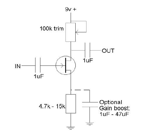 I love that open tubey sound of a mosfet or jfet booster, it just opens up the sound of an instrument, which I want to push a Ge second stage booster to get a little grit and add that Ge magic. Since I want o put this all on one board as one circuit, I'm going to have the output of the first stage controlled by a trimmer, so that the voltage going into the second is controlled and the drive of the Ge stage is controlled. The second stage I just want to have an external pot to control the overall output of the pedal. Now with high pass and low pass filters, I just have such a hard time trying to understand how to find the "right" values for the resistor and cap. I've read three different electrical engineering books, read forum posts, searched online and it doesn't sink in. I read both of the books from Bryan Wampler and he gives the table below to help with determining high pass and low pass filters, but it doesn't seem to provide combos for lower bass frequencies, which I believe go down to 32Hz or 64Hz for low C, and when I put the combos into the AMZ R-C Calculator I never get the same frequencies he provides, which is why I think I'm getting more confused. On another note about filters, I've been wondering is it possible to change a high pass filter to a low pass filter and when should each be used? 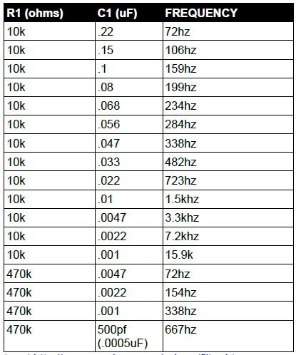 I swear every time I think I'm getting ready to try and make a layout for this project, I jump back to the breadboard and have more questions. But, slowly everything has been making more sense, so I don't feel like such a noob anymore. lol |
«
Return to Open Chat
|
1 view|%1 views
| Free forum by Nabble | Edit this page |