No, not that silly British holiday after Christmas...

I thought I post some photos and text of my Tokai Metal Drive build to illustrate my basic boxing process (with a few twists). Hopefully this will be of interest to the group.
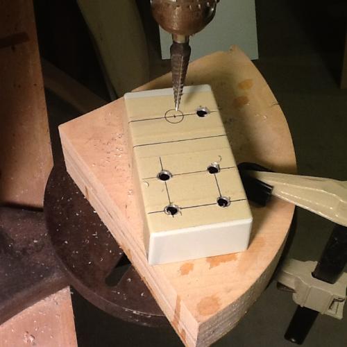
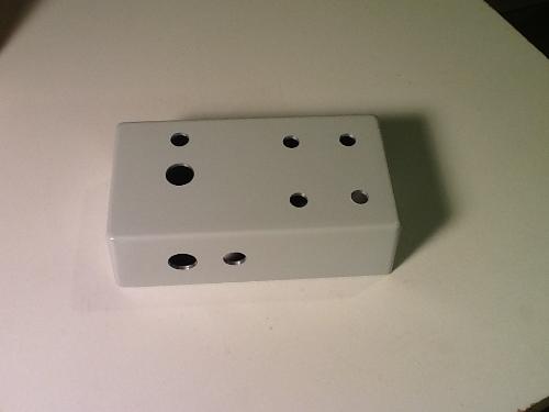
(1) Drilling the enclosure.
I get pre-painted enclosures from the usual sources and drill them myself with a unibit on my old drill press. I use masking tape to mark the hole locations, which also protects the painted surface.
(2) Mounting the pots and planning the circuit board installation.
After removing the tab on the pots, I mount them in the enclosure an check my clearances (especially with respect to the input/output jacks). The TMD has a complication in that one of the pots is a dual gang and hence sits higher that the other pots. To correct this, I use thin 2mm foam from Walmart to make square spacers. I also use the foam to mount the circuit board to some plastic perfboard which will sit on top of the pots.
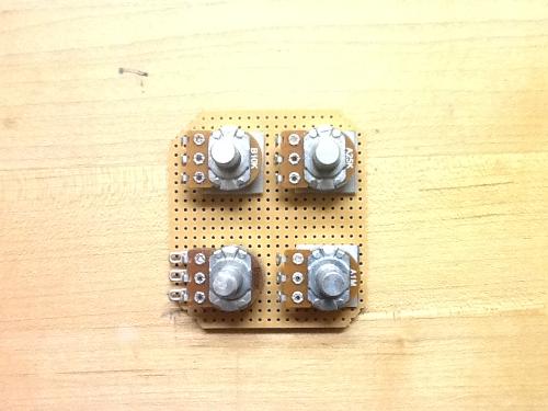
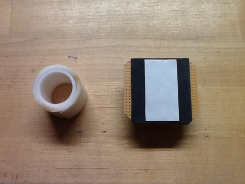
(3) Creating the pot-mounting assembly.
I glue the square foam bits to the back of the three single gang pots using gel superglue. The perfboard is glued on top of that. I also use gel superglue for that, but epoxy may be better for the long term. The assembly looks like this.
(4) Attaching the circuit board.
I attach the circuit board to the foam on the perfboard using a double-sided adhesive tape from the art store (acid free mounting tape). I only use a small piece, and that is strong enough (trust me). The back of the vero embeds safely into the foam, ensuring that nothing will short out.
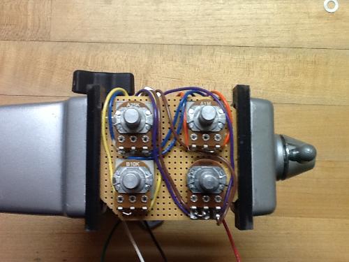
(5) Wiring the pots.
I now attach the wires to the pot lugs. This is done VERY carefully to make sure I don't mess up the order. Nothing like having to remove solder from mis-wired controls (grrrr...

).
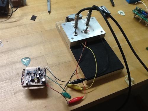
(6) A quick test...
I check out the completed assembly using my test rig. Yup...it still rocks and the controls work as they should.

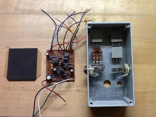
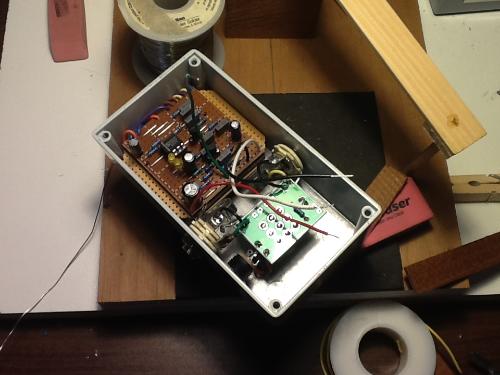
(7) Securing the assembly into the enclosure and wiring up the off-board components.
The remaining work is standard off-board wiring. I use the 3PDT boards from Vic Audio which greatly simplifies the process for me.
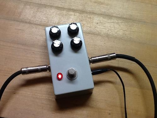
(8) Done and ready to rock!
Well, except for the labels. I've not adopted any labeling or artwork for my boxes yet and may just go with a hand painted lettering to give it that "boutique" look. Now, onto the Klon...

.


 )
)
 .
.
 )
)
 )
)