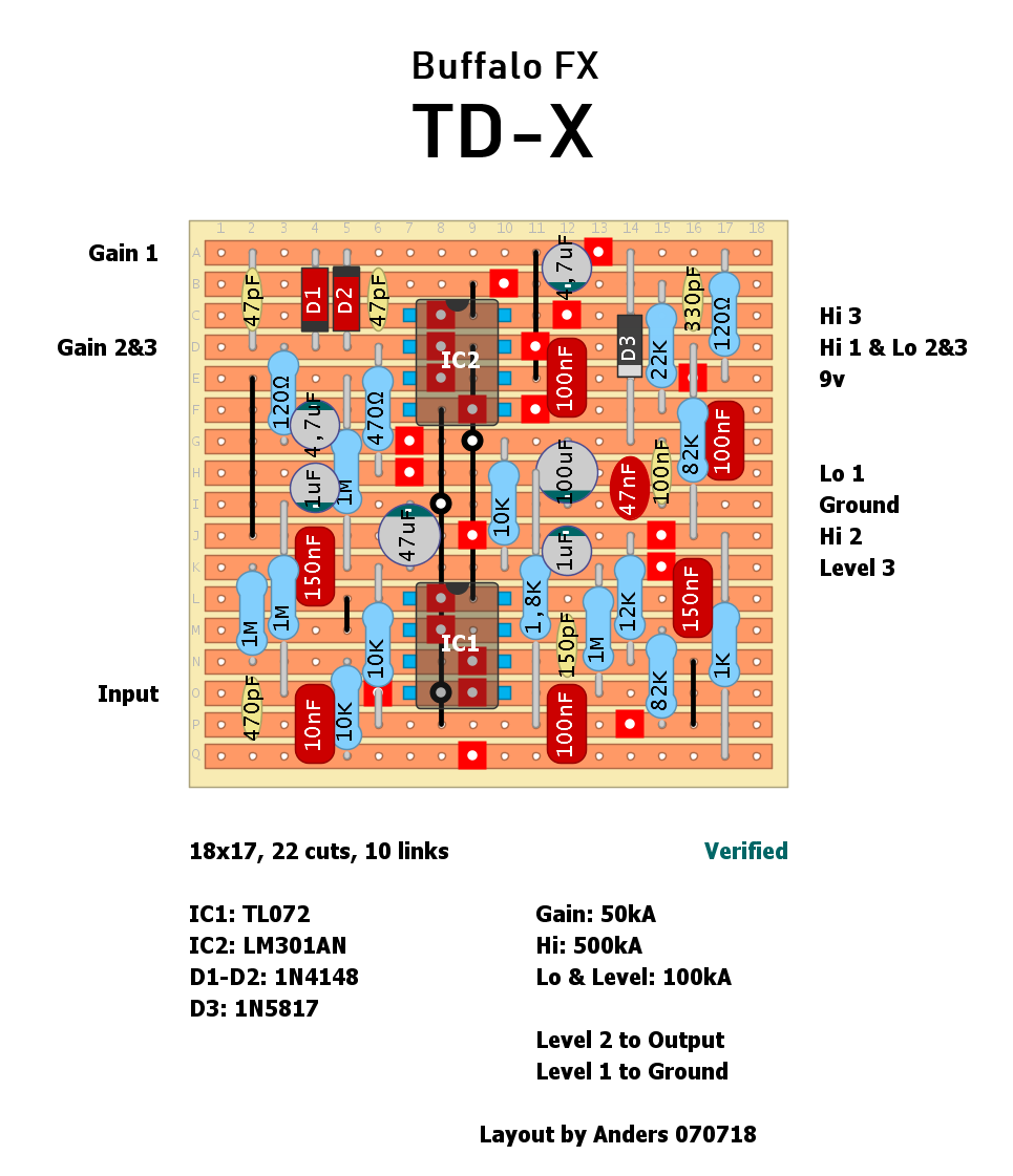
Buffalo Fx TD-X - Verified
12

12
|
This post was updated on .
|
|
Hi
I have the Original & it is an awesome pedal. If you are chasing the Gilmour Pink Floyd Tube Driver sound then this is What you need Awesome Demo's Part 1 https://youtu.be/sVcXuQ2sLGo Part 2 https://youtu.be/47Y8YAbFngQ Cheers music6000 |
|
Alternatives to LM301AN ic?
|
|
Since the 301 has the frequency compensation cap (between pin 1-8), in theory you would need to use a similar opamp, e.g. 101/201/308, and they might need to have the cap value tweaked to get a similar response depending on how the spec differs from the 301. However, since there is a pair of anti parallel clipper diodes in the loop and we're talking about a dirt pedal here, you could probably pop any single opamp with the same pinout and it would work and sound pretty similar if not indistinguishable, e.g. 741, TL071, 5534 etc. If you choose one that doesn't use a compensation cap you could just leave out the 47p from pin 1-8.
|
|
Thanks.
I've got lm741s and tl071s. So they don't need the cap, right? |
|
In reply to this post by nocentelli
Thanks.
I've got lm741s and tl071s. So they don't need the cap, right? |
|
Correct. I believe they have an internal compensation cap. In the pinouts of LM741 and TL071, pin 1 has the "offset null" function (along with pin 5) and pin 8 does nothing. You could just leave off the 47p cap and then if you want to swap in a 301 at a later date, you can just solder in that cap too.
|
|
I've built the layout this afternoon.
I finallly used a lm741with no compensation cap. Didn't try it yet, but looking at the schematics, the electrolitic cap after 12k resistor seemed to be reversed. Let's see if I finally can find a decent mid gain overdrive for my Hiwatt. Tomorrow will give it a try. |
|
This post was updated on .
You can tag it as verified, it sounds great!
Tried with the lm741, but it didn't work, (just a low volume gritty sound). I don't know if it was faulty or something, but a TL071 worked great there. I soldered the electrolitic backwards as per schematics and everything seemed ok. It sounds very amp like and that eq is awesome. Tried on a Fender twin and reminded me a lot to a catalinbread dls mk3. On my Hiwatt it sounds like a superclassy and refined hotcake, which is something I've been looking for for ages, so this thing is a clear winner for me. Tried boosting it with a nagaviper in front with my strat bridge pup selected and holy s**t!! I may mess with it a little though. May be I will try a lower treble cap and different silicon diodes for fun. The bass pot comes up pretty fast for my taste, so I may try a linear there. All electrolitics are over 35v, so I was wondering if I could power this with 18v without burning something... |
|
Finally I found some lost ca3030/op07 IC's. Compensation cap on ca3030 didn't make a difference to my ears, (even when removed it).
Lm741worked with no problem as well. I just tried it on IC 1 shocket by mistake... I found all of them very similar, but none of them sounded bad at all, what made me think in not going for the original lm301. The bass pot was wrong as well as I put linear there instead of the log. Now it's working like it should. What I did found common to all IC's was a slight but audible fizz on notes and chords decay, (hotcake like). Any experience on that? It wasn't so annoying, but I though that maybe increasing the headroom of the IC's could make things better. Love this thing. Is not so transparent at all, but it could make it as one of that foundation pedals at the end of the signal chain with no problem. It's so damn dinamic, that I could even get a good sparkly clean with a cranked nagaviper in front of it by just rolling down the guitar volume |
|
Cool! Thanks for verifying! Layout is updated.
Ok, you have made me tempted to build this myself |
|
You do it!
It´s a no brainer straight forward layout with no fet biasing involved that sounds very amp like. |
|
Is it possible to add a mid pot on the tone stack? Or will that make the circuit sound bad?
|
|
You could try a pot between tone stack 47n cap and ground and see what happens, (just saying...)
|
|
This post was updated on .
A cool thing I tried this afternoon; a 2PDT on-off-on clipping switch. Original pair of diodes on one side and 3 silicon on assymetrical configuration on the other.
This last setting opened the sound in general and let more mids come through. Leds were even cooler, but it bearely made any difference in sound when comparing it with the no clipping setting, which was so cool as well indeed... I think that this effect could even handle something like 3 germanium diodes on assymetrical configuration as a step up in clipping compression |
|
In reply to this post by anders
I saw an internal picture of TD-X; on pcb there is a transistor. Why in your layout i don't see it?
|
Re: Buffalo Fx TD-X - Verified
|
Probably a milenium bypass for LED indication. Just guessing though.
|
|
In reply to this post by traktop
It's an interesting idea to try different clipping diodes - this circuit probably warrants further experimentation. I built it as per Anders' layout (thanks Anders!) but used a TL072 and TL071, without the compensating cap. It's a cool overdrive with tons of clear low end, which is rare. It works extremely well with a Strat which again is rare IME if you don't want another TS! But it also sounds great with a Gibson with P90s.
I think I may have found another go-to overdrive. :-) It is different enough from my fave - a Rockett 45 Calibre - especially in the midrange. I can definitely hear some Gilmour in the tones. Thanks Anders!! |
|
In reply to this post by anders
Hi all,
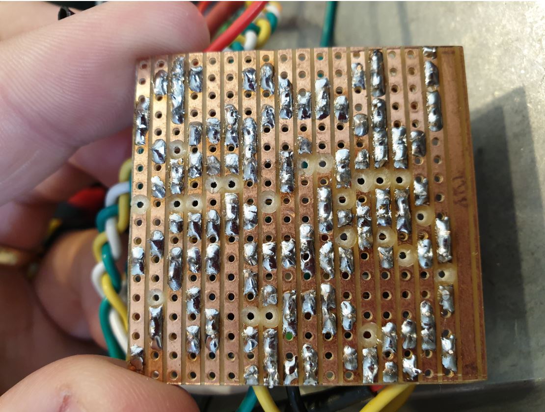
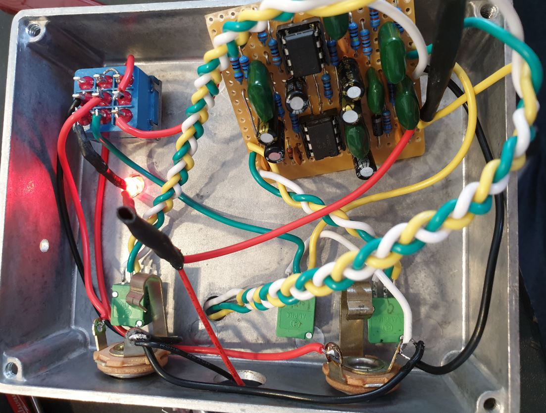
First time posting. Appreciate some troubleshooting help:-- I've been working on this build and upon testing, it's completely dead when engaged. I've double-checked the 3PDT & jack wiring, and the cuts/links/layouts on the board. I found I'd put the 47uf electrolytic cap the wrong way around, and have replaced that correctly with a fresh capacitor. Took some key voltages that may help with troubleshooting: 9v in - 9.3v 9v in resistor (120R) - 3.6v D3 (1N5819) - 3.2v IC1: 1 - 0.9v 2 - 3.3v 3 - 2.8v 4 - 0.9v 5 - No reading 6 - 1.1v 7 - 2.2v 8 - 0.5v IC2: 1 - 3.3v 2 - 0.6v 3 - 0.6v 4 - 1.0v 5 - No reading 6 - 0.3v 7 - 2.2v 8 - 2.2v A couple of things that jumped out at me (even though I have no idea): - 3.6v across the +9v input resistor - I tested it on the same battery before I put it into the board and it was around 9.0v (can't see any bridges or reasons why it would drop so much?) - Pin 2 of IC 1 and Pin 1 of IC 2 both read 3.3v (thinking Pin 1 should be similar?) - Pin 4 of both ICs should be ground (confirmed with schematic and multimeter, so I'm not sure why there's a small voltage here)   Ben. |
|
Hi Ben,
Looking at Your photos I can see that You did assembled layout MIRRORED as it not should be. You did all cut holes from Copper side whereas You should do from laminate side. Please read guide here:http://tagboardeffects.blogspot.com/2012/04/vero-build-guide.html Regards |
«
Return to Unverified Layouts
|
1 view|%1 views
| Free forum by Nabble | Edit this page |


