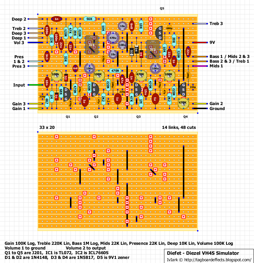
"Figure out which side of the cap touches the part of the circuit with a DC shift and put the positive leg there. Both of the 100n caps in question on the Diefet are an example of this. The one connecting the Deep control to the Volume control is an output cap. The Deep control is connected to the final op-amp stage (DC biased to Vref) and the Volume control is connected to the circuit output (ground). The other one connects to the input of the final op-amp stage (again, DC biased to Vref) and the other side connects to the tone stack. Notice that there is a DC path to ground on this side (through the TMB pots) but no DC path to the supply voltage, because the signal path from the previous jfet stage passes through other caps before it reaches the 100n. Thus the DC bias on this side should be zero."
I am trying to understand the phrase "Figure out which side of the cap touches the part of the circuit with a DC shift and put the positive leg there." Okay - so DC shift means there is a coupling cap which is changing the state of the DC (or eliminating it) for the coupling of sub-circuits within a larger circuit, because one side has different DC requirements from the other side. So, in this case both 100n caps have one side connected to Vref and the other side eventually going to ground. The DC bias on the side of the 100n caps that goes to ground should have 0 bias - is that correct?
diefet_schem.jpgIn other words, when you say "Figure out which side of the cap touches the part of the circuit with a DC shift and put the positive leg there" - that means to put the positive side on the side before the bias shift? and that the ground goes to the side after the bias shift? Meaning the "shift" is from a section with a DC+ bias containing the IC, to audio subsections (the tone stack and the volume pot) where we really do not need DC. Am I on the right track, or completely off base?
(also - sorry about the earlier mistake, I don't know why I was thinking diodes when we were talking about caps).
I actually just noticed the original schematic is here:
http://techniguitare.com/forum/ressources/image/1663