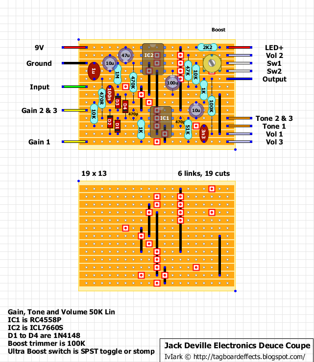
So last night, I thought I'd do a quick build of a circuit I've been meaning to try out for a while, the Jack Deville Deuce Coupe:

I just got some charge pump chips last week, and this was a simple project. Everything went together very smoothly. So I fired it up and...no overdrive! Just a unity gain signal.
I then spent the next two hours probing, testing, measuring voltages, changing chips...nothing. WTF???

I was sitting down later looking over the schematic when it suddenly dawned on me. That "1u" capacitor on the left?? Yep - I had used a "1 nF" capacitor instead!! Oooops....

It so happens that this capacitor is in the ground leg of the op amp feedback loop. The op amp gain for the non-inverting configuration in the Deuce Coupe is: Gain = 1+Zf/Zg, where Zf is the impedance of the feedback loop and Zg is the impedance of the ground leg attached to the inverting (-) input. Using a 1 nF cap made Zg increase by several orders of magnitude (over the normal effect frequency range of 50 Hz - 10000 Hz)! Hence Zf/Zg ~ 0 --> Gain = 1 --> no amplification. Duhhh.
So if you ever have a problem build and can't figure out what's going on, keep an eye out for capacitor dyslexia...

(There is also a related malady known as "resistor dyslexia" where 470K ohm resistors are used instead of 47K, 4.7K, or 470 ohm resistors...)