Cardinal Trem difficulty

classic Classic list List threaded Threaded
11 messages Options
Reply | Threaded
Open this post in threaded view
|

Cardinal Trem difficulty

Skajaquada
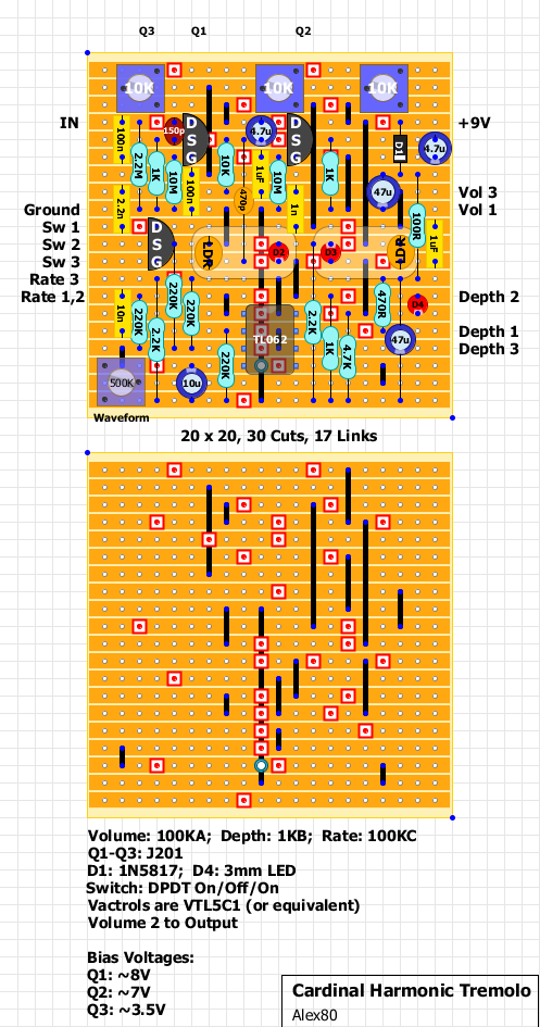
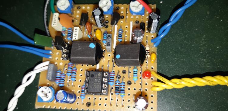
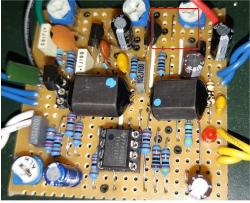
Hey guys, I had posted this in the wrong spot, so I'm reposting here.  I'm referencing the Cardinal Tremolo layout posted by Alex in the "verified layouts" section on the forum.  I'll insert the image of the layout I'm using in this thread.

The only control that seems to work for me is the Volume.  The Rate, Depth, and Waveform pots/trimmers do nothing.  The switch does nothing either, except in the bottom position, it cuts all sound completely.  The only sound I'm getting is an unpleasant overdrive.

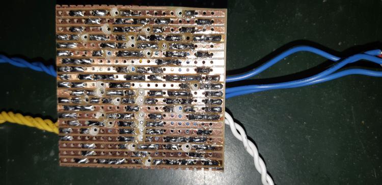
I've gone over the usual things - checked my tracks for solder bridges, double and triple checked the layout to make sure I had everything in the right place.  I've noticed two things:

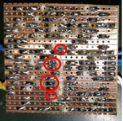
First, the upper portion of the layout doesn't match with the "partsless" portion of the layout which shows cuts and links.  The link at the bottom of the TL062 is one row shorter in the bottom view, and the link on the rightmost 10K trimmer is two rows longer in the bottom view.  I don't think the link for the trimmer matters either way, but the link on the IC seems like the longer one is correct.

Secondly, I've checked my bias of the three J201s, and my Q3 is acting wonky - I bias it to ~3.5V but after I set it, I play a bit to test, and recheck the bias which shows over 8V and then slowly falls back down to the 3.5ish volts I originally had it set to.  Does this indicate a bad J201? Or might the links have something to do with it?

I built the trimmer layout and my links followed the bare view, but I redid the TL062 link to match the top view.

Any thoughts?  Not really sure how to proceed at this point...

Edit:  I should also say that I'm using an SPDT on-off-on switch rather than a DPDT, since only 3 lugs were used.  Unless the lugs are supposed to be numbered left to right, rather than as IC pins are numbered?

Reply | Threaded
Open this post in threaded view
|

Re: Cardinal Trem difficulty

Skajaquada
Alright, so still having problems with Q3.  Been checking it many times over, and even pulled it out, socketed it, and replaced it with another J201 only to have the same problem.  I can't get a constant voltage out of it at the drain.  On two switch positions, I'm getting nearly source voltage, and on the third position, I'm getting between 4 and 5 volts - but on every switch position, the voltage fluctuates.  Where Q1 stays at almost exactly 8V, and Q2 stays steady at almost exactly 7V, Q3 is just not cooperating.  I've even gone over every trace I can see that leads directly to Q3, but there aren't any bridges or anything, and I'm sure the links and such are in the correct place.

I even replaced the TL062 with a TL072, just cause it was easy, but no change.  Can anybody offer any insight as to what I should check?  I'm drawing a blank.

Thanks in advance.
Reply | Threaded
Open this post in threaded view
|

Re: Cardinal Trem difficulty

Skajaquada
In reply to this post by Skajaquada
Update #2:

I replaced the middle trimmer (for Q3) to a 20k - although I really think all the trimmers should be 20k in my case.  Just not enough resistance to bias my J201s properly...

Anyway, I noticed that I was able to bias Q3 to ~3.5V finally!   ...but only when the spdt is in the up position (i.e. connecting lugs 2 and 3 together).  When the spdt is in either of the other two positions, I get source voltage on Q3 and the only sound I get is a nasty sounding overdrive.  When the switch is in the bias-able position, no sound at all...

I've checked all my cuts and traces at least 20 times now, and I'm sure the cuts are proper, and the links/components are all in the correct places.

I've also noticed that none of the 4 lugs on either vactrol is registering any voltage at all, and I'm guessing that's part of my problem, but again, I'm at a loss.  I'll attach a couple photos of my board for your consideration.


Reply | Threaded
Open this post in threaded view
|

Re: Cardinal Trem difficulty

Marbles
Hi, that's a tough one. Did you knife it? There are some suspect spots. I'm sure you checked:


Reply | Threaded
Open this post in threaded view
|

Re: Cardinal Trem difficulty

Marbles
In reply to this post by Skajaquada
Also, underneath the TL062, there should be a double link. From the front it looks like you did, but the bottom picture does show the hole still (even though there's solder around it).
Reply | Threaded
Open this post in threaded view
|

Re: Cardinal Trem difficulty

Skajaquada
Hey man, thanks for the tips.  I have gone over the board with a fine toothed comb, and I'm sure there are no solder bridges.  The suspect areas are likely just reflections from the camera flash.  With regards to the double link under the TL062 - the reason there's solder around that one hole is because the link extends below the double to two different places, depending on which part of the layout you're looking at.  The populated picture shows the link extending to the last row, while the bare picture shows the link extending to the second-last row.  I had it on the second-last row initially, but changed it to the bottom row afterwards, thinking that might help.  It didn't...

I appreciate the help though, if you notice anything else, please let me know.  Cheers.
Reply | Threaded
Open this post in threaded view
|

Re: Cardinal Trem difficulty

Marbles
Could you check this link?


Reply | Threaded
Open this post in threaded view
|

Re: Cardinal Trem difficulty

Skajaquada
Yeah, that link is the other discrepancy between the two layout views...  I left that one as I had it because it looks like it functions the same way either way.  It does work to bias Q2, it just looks like if I used the short link, the only difference would be the direction of the turn on the trimmer.
Reply | Threaded
Open this post in threaded view
|

Re: Cardinal Trem difficulty

Marbles
Ah yeah sorry, too caught up in comparing the layout that I Stop thinking about it :)

I don't know. The only thing I can offer is an extra set of eyes. And like you said: You've gone over everything. The only thing I can't see correct is the switch wiring cause they 2.2n cap is move up 1 row. But judging the bottom of that board this seems right too.
Reply | Threaded
Open this post in threaded view
|

Re: Cardinal Trem difficulty

velouriafx
I built this trem one time with this layout. I don't remember exactly what I mod, but I believe I changed the 4.7k or the 2.2k resistor by 1k and the effect appears.
Reply | Threaded
Open this post in threaded view
|

Re: Cardinal Trem difficulty

velouriafx
the schematic of the 1776 is offline, but looking at the layout the connection of the Vactrol LEDs does not make much sense. They are only linked to the ground, are they not?