Catalinbread Sagrado Poblano Picoso -- vero layout summarizing page ('19)
|
This post was updated on .
edit: the whole thing -- to make this post -- came up as I wanted to make this small enough to be put into a bass guitar's body...
not realizing that this is not an onboard preamp... :) :) as it doesn't have a buffer section :) today I just looked at the 47pF capacitor going to the ground, and started thinking but where is the resistor that usually would be there, too.. to make the input impedance high enough ... then I understood why everybody was putting this into a pedal :) cause the pickups' signal will NOT go into this... so, please excuse me for this almost completely unnecessary post :) why it is worth keeping it is because it lists (absolutely) useful links... and displays the schematic, too - - - - - - - - the original post: hi, the reason for this post is twofold... first, I am in the making of a Catalinbread Sagrado Poblano Picoso instance, it is resting in my kitchen as we speak :)
I was building it following the layout by Mark at tagboardeffects.blogspot.com... I'll call them FLAT.. FLAT-A, and FLAT-B... and I'll call Mark's version the ORIGinal... so, purpose no. 1 of this post: sharing + 2 layouts of this circuit... and the schematic, which was not so easy to find, when I was trying... and purpose no. 2 is to summarize the info, knowledge, conversations, and to share the links to them... including the schematics, and Mark's ORIGINAL layout... - - - - - - - - - - - - - - - - - - - - - - - - - - - - - - - - - - - - - - - - - - - - - - - so... here is the schematic by Edwin Thoen and Silent Fly // LINK 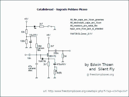
- - - - - - - - - - - - - - - - - - - - - - - - - - - - - - - - - - - - - - - - - - - - - - - and here's the ORIGINAL layout by Mark // LINK 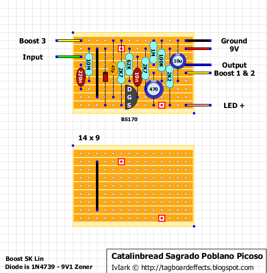
- - - - - - - - - - - - - - - - - - - - - - - - - - - - - - - - - - - - - - - - - - - - - - - and... here are the links:
I'll post the schematic and layouts just below.... (the layouts are NOT YET verified!)(but I'm working on it, even as we speak :)) ... Aug. 25..2019 |
|
This post was updated on .
so, here is FLAT-A... The flat version, using "lying" CAPs...
I also uploaded the DIYLC file "Catalinbread-Sagrado-BASS--FLAT-A.diy" (see below) 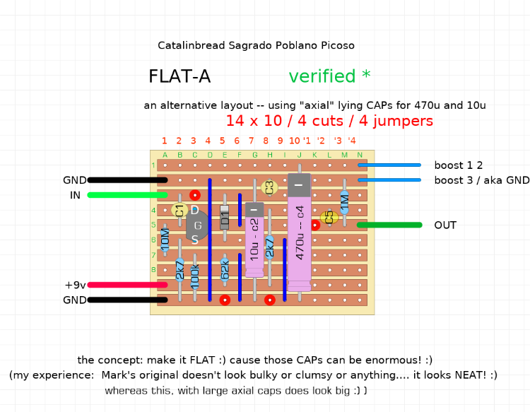
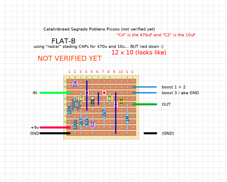
and here is FLAT-B :) -- using standing electrolytic caps laid down...
- - - -
and here are the DIYLC files: Catalinbread-Sagrado-BASS--FLAT-A.diyCatalinbread-Sagrado-BASS--FLAT-B-v2.diy ... |
|
In reply to this post by j-pee
A simple solution would have been to solder some left over cutoffs from other component legs, to the legs of the cap.
Don't worry about what it looks like, it's homemade, and going into an enclosure where it will never be seen. |
|
that was exactly my first thought :)
but the veroboard... (the stripboard) as a phenomenon cuts your desires for freedom loose so vividly :) I mean, it is so mathematical.. so clean, so ordered, and so much under your control... so, why shouldn't we get exactly what we want? or.. why would we be content with less than what we exactly want? I'm also talking about the big caps which would make the board BIG... I never placed any circuit into the body of my passive bass.. but I know its cavities, and I'm aware that space matters :) and I imagine this circuit as an onboard preamp... I can't wait to hear it anyway... |
|
I think we all have our own likes/dislikes/ways we prefer to lay things out. I often redraw layouts to suit my own particular anal tendencies. In my world I use multilayer ceramic caps for the pF sizes and they span 3 rows. So I like them to span 3 rows so no bending is required - two rows is ok at a pinch, as is four. But ideally? Three. As I use mainly box caps for the nF ranges three rows is preferred there too. I will go to two row spans if I really have to because you can tuck the wire under the cap and it still looks neat. But four or more rows is something I really try to avoid.
I love it if I can put electrolytics over just two rows but for whatever reason I'm not as anal about them. But I do try to leave space for them. I hate layouts where on the drawing there is space but in reality it's too crowded. And that may well be the case in my hastily redrawn layout here. 470uF caps can be enormous compared to everything else on one of these layouts. I also like to have inputs and gains on the left - preferably gain above input - and output on the upper right side. So this is how I would redraw the Catalinbread booster - It's not verified, I just drew it to illustrate how you can easily swap things around if you want.: 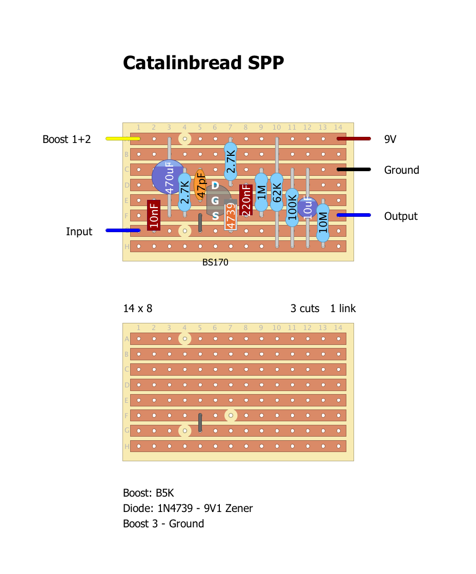
|
«
Return to Unverified Layouts
|
1 view|%1 views
| Free forum by Nabble | Edit this page |

