Clari(not) Cubed LFO Mod-VERIFIED
|
This post was updated on .
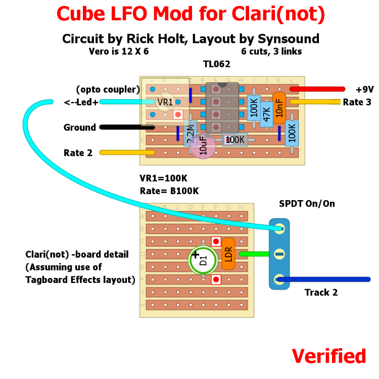
****PLEASE NOTE: The layout has been corrected and now shows the correct vero dimensions.
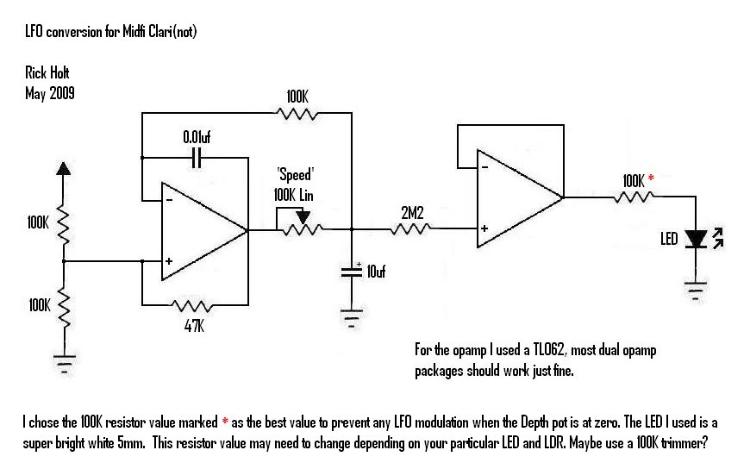
I've been working on this for a few days and am happy to say it is now VERIFIED! I put this together from one of Rick Holt's schematics and must say it adds a whole new world of usable settings to this effect. In addition to the stock sounds it now provides mild to sea-sickening chorus and vibe effects as well as other weird warped vinyl and stretched tape sounds. Thank you Mr. Holt! I set it up to be switchable between stock/ envelope and LFO driven modulation. I included the recommended trimmer to dial in the best LFO range. I also followed his suggestion of using an ultra bright clear LED and paired it with a Tayda LDR. This is way better than the effect I alredy loved. I hope someone can make use of it and love it like I do.  Here is the schematic by Rick Holt: 
Give a man a match and he'll be warm for a day.
Set a man on fire and he'll be warm for the rest of his life. |
Re: Clari(not) Cubed LFO Mod-VERIFIED
|
Sorry if I'm missing something, but where is the opto coupler in your layout connected? I have yet to build the clari(not), but this is pushing me toward it. I've built the pitch pirate deluxe, how does this compare?
|
|
This post was updated on .
The LED out of the top board goes into the switch(lug 1). It then goes from the switch (lug2) to the LED + of the ClariNots optocoupler(represented by the LED/LDR combo on the bottom board.) That line from SW2 will connect where the Tracking 2 connection would have gone in the standard layout.
Give a man a match and he'll be warm for a day.
Set a man on fire and he'll be warm for the rest of his life. |
|
This post was updated on .
In reply to this post by SonusFluxa
I didn't have much luck with the Pitch Pirate Delux. I may try again in the future. I did build the standard pitch pirate and think this mod for the Clari gives a much smoother LFO. That could be because of the LED/LDR combos? From what I can tell this mod basically creates all of the pitch pirate functions aside from the wave shape control but adds envelope and fuzz. I may just bypass the fuzz on mine to get all of the controls to fit. I have plenty of muchore adjustable fuzzes to put in front of it anyway.
Give a man a match and he'll be warm for a day.
Set a man on fire and he'll be warm for the rest of his life. |
Re: Clari(not) Cubed LFO Mod-VERIFIED
|
I would definitely recommend the second layout posted in the forums for the pitch pirate deluxe. I haven't taken it off of my pedal board since I built it a few months ago, I totally love it. I saw your request for information on more repeats for the clarinot, and I think the pitch pirate can satiate that need (or at least it does for me).
Built this LFO the other day, and your instructions totally made sense when I had the board in front of me! Thanks for the layout and an awesome addition to an awesome circuit. |
Re: Clari(not) Cubed LFO Mod-VERIFIED
|
In reply to this post by Synsound
Thanks for this layout! I'll just pop the out its actually 12x6 ;) I cut mine 11x6 and ended up soldering some stuff on the back hehe
Thanks again. -Brett |
|
Sorry for the misprinted hole count. I'll try to fix that ASAP. I hope you enjoy the lfo.
Give a man a match and he'll be warm for a day.
Set a man on fire and he'll be warm for the rest of his life. |
|
The layout has been corrected above. Thanks for letting me know.
Give a man a match and he'll be warm for a day.
Set a man on fire and he'll be warm for the rest of his life. |
Re: Clari(not) Cubed LFO Mod-VERIFIED
|
Hey so I built this up in february when we last talked about this (it looks like) and then I never got the LFO working, so I went and looked at the board and tracked down the schematic (which you have here).. and It seems to me the wire out to the switch which then goes to the LED+ in LFO ON mode.. is one row too high.. as per the schematic the inverting input and output 1 are tied together and then go through the 100k resistor (which we have as a trimmer in this layout). But with that top jumper, that side of the trimmer is just a short, so there is NO resistance on that end of the trimmer before the LED+ out.. and I'm thinking that's why the cut 3 in and 3 down from the top left corner is there?
Anyway I just thought I'd ask. -Brett |
Re: Clari(not) Cubed LFO Mod-VERIFIED
|
Yeah. I attached it to the 3rd row down, and it works now. Pretty freakin cool. I've messed around with the trimmer for the LFO brightness, you can get some super swampy sounds going. I got a 2M LDR and a UV water clear going right now and it seems to be the best to my ear... very fun mod. Thanks again
-Brett |
Re: Clari(not) Cubed LFO Mod-VERIFIED
|
In reply to this post by Synsound
Hey man. I built this, and hooked it into my Clari(not), but I'm a bit confused about the top left corner...
I assumed that the LED+ was just a separate LED, since the middle lug of the switch connects to the clarinot LED+. Is that correct? Just a floating LED that flashes with the rate? Also, the trimmer doesn't seem to do anything. It says that it's supposed to be for LED brightness, but I'm not seeing that. I'm thinking I'm just confused about that part of the mod. Is it supposed to be just a separate LED, or a separate LED and LDR combination? If the latter, I don't really understand how it's supposed to be hooked up. Can anyone offer me some clarity? Much appreciated, Skaj |
Re: Clari(not) Cubed LFO Mod-VERIFIED
|
yeah it hooks up to the Clari-not LED.. but read my above post. The layout has the trimmer and wiring for it hooked up one row off, I had to sneak the wire in under the trimmer and then it started working.
-Brett |
Re: Clari(not) Cubed LFO Mod-VERIFIED
|
In reply to this post by Skajaquada
Sorry to Double post, but yeah the wire that says "LED+" has to go down to row 3 where the cut is, unfortunately i had cut my board already so I had to sneak it next to the leg of the Trimmer. If you look at the included schematic it should make sense!
-Brett |
Re: Clari(not) Cubed LFO Mod-VERIFIED
|
Thanks man. I'm gonna give this a shot tomorrow and see if it works. Appreciate the reply!
-Skaj |
Re: Clari(not) Cubed LFO Mod-VERIFIED
|
Sure man. I just built a second one of these and it works with the wire down on row 3. I actually used a dpdt switch to hook a second Led up in series through the switch, so when you turn the LFO on it engages two leds in series. Then you use the trim pot to adjust the brightness and have yourself a rate led on the top of the pedal. Boom.
-Brett |
Re: Clari(not) Cubed LFO Mod-VERIFIED
|
Worked a charm! Thanks again for the clarification.
-Skaj |
«
Return to Mod Boards
|
1 view|%1 views
| Free forum by Nabble | Edit this page |

