Combining effects (3 in one)
12


12
|
Hey guys
Recently I was requested by a friend to do a bigger project. He wants to have a a Fulltone Plimsoul OD and a DBA Fuzz War ..eventually a reverb effect as well - all under one Box. Wanted to ask your opinion about it and generally if someone can supply good links for the combining theory. and specially I am thinking - how does it works with the power supply ?? how to supply 2 or 3 circuits with 9 V power ? should there be an Amperage pump for that, or some motherboard that supply each effect seperatly the power needed without faultiness ? how does it work with the 3PDT switches ? when we also would like to treat each effect that is in the unit individually and engage it without relaying on the others ? many question marks.. I know, thank's for the attention. Any kind of support will be highly appriciated! A. |
Re: Combining effects (3 in one)
|
Most power supplies designed for pedalboards have a large current capacity already, somewhere in the neighborhood of 1-2A. A Plimsoul and a Fuzz War won't take up that much current; the reverb might take a little more depending on its topology. I wouldn't worry about it too much. One DC jack connected simultaneously to all three pedals is more than sufficient. You can either put power filtering on each effect board then forget about it or make some kind of daughterboard that has the filtering on it before you distribute it among the effects, wither way works fine. As far as switching, just treat each individual effect separately (pretend you're making three separate pedals when you do the switch wiring).
Through all the worry and pain we move on
|
|
Administrator
|
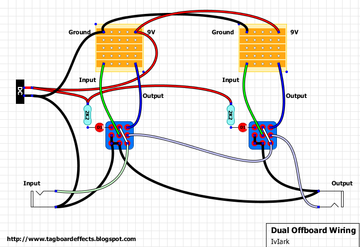
just to add to what silver said. mark had posted how to wiring a dual effect in one enclosure, see below.
 so if you wanted have 3, 4, or more you would just continue the pattern in the wiring. you can use 1 dc jack and have as many wires as you have effects coming off it. |
|
that's a start. Well I did notice this dual effect wiring. Still I am concerned - is this the way to wire so taht each effect will work individually as well ? or when engaging one, then all receive electricity ?
And what are these filtering that Silver mentioned ? I don't seem to get that - might be what I aim. |
|
Administrator
|
both pedals will have power as long as there is power plugged into the dc jack, the switch is controlling whether or not the signal goes through the circuit or not. so both effects will work independently from each other, ie: you can control them separately.
i think what silver was talking about is that the power supply can support more then one effect, but sometimes cheaper ones have a fluctuation in power, so if you add a power filtering cap to help keep the power flow constant. |
|
In reply to this post by Tune Tone
I've built a 4 effects box (muff/mammoth/naga viper/Zen) all using the same power DC with no issues. I link all the board 9v into one as it is easier to solder just one wire to the DC. As for the switches, just wire it as per the diagram above. They'll all switch on/off individually without interfering with other effects.
|
Re: Combining effects (3 in one)
|
The wiring I mentioned and the above wiring will ensure that each effect works individually. There's nothing here that does otherwise. Each effect gets its own 3PDT bypass switch and LED, there's no overlap. Just take that wiring scheme and add a third board/switch and you're good to go.
Regardless of what kind of pedal you build, electricity will always be applied to the circuit so long as the power supply is plugged in. What you're switching is the input/output, not the power. (Battery-powered effects get around this by using a TRS input jack whereby the battery is disconnected when there's no cable plugged in but this obviously doesn't apply here (just an example).) Filtering includes power supply filter caps, polarity protection, current-limiting resistors, RF interference damping, etc. Like I said, if you build verbatim layouts from here most boards have this already and you don't need to worry about it, but if you wanted you could make one central power filter to apply before you distribute power to the effects.
Through all the worry and pain we move on
|
|
Thanks SIlver.. now I get the filtering thing you mentioned and yes it is already done by most layouts I built from here.
Can you forward me or recommend a good reading to some layout to do this kind of central power filtering ? experimenting with such things which aren't effecting the sound of the effect might be good for me as I am still noobing this thing out .. so for better understanding. thanks a bunch |
Re: Combining effects (3 in one)
|
Uh, well I don't know of much reading you could do, it's a pretty simple concept. Really thorough filtering in our case really is just:
1. A reasonably large filter cap from +V to ground (47-220uF), and one from Vref to ground if there's a Vref, 2. A reverse-polarity protection diode (ideally a low-forward-voltage Schottky rectifier diode, e.g. 1N5817) in series, ideally, with V+ (parallel works too, but has self-destruction risk) 3. A small-value (10-100Ω) CLR in-line with V+, before the cap, 4. A smallish-value (~100n) ceramic cap in parallel with the filter to scour out any high-frequency noise And really, in most cases, only #1 will be necessary. General topological order is (V+)>(Resistor)>(Diode)>(Cap)>(Cap).
Through all the worry and pain we move on
|
|
I am going to try and make the Reverb in this 3 in 1 project turned on / off from a toggle switch.
did someone tried that before ? So the Plimsoul and Fuzz War are normal engaged with a 3tdp switches and the revervb I want to use is the layout of JohnK of the Wampler Faux Soring Reverb. But then again... how do I do the reverb turned on from a toggle switch ? |
|
A 3PDT toggle switch is wired exactly the same as a 3PDT footswitch. On the lug-side, they are identical. So just pretend it's a footswitch. No need to change anything.
|
|
In reply to this post by Tune Tone
|
|
In reply to this post by induction
Yes I see.. but why would I would to use a 3pdt switch and not a 2pdt one ? the switch should deliver the signal through the reverb circuit when its on and when off simply skip the reverb circuit and go straight to the output.
|
Re: Combining effects (3 in one)
|
Third pole is for an indicator - if you don't want one, feel free to use a DPDT.
Through all the worry and pain we move on
|
|
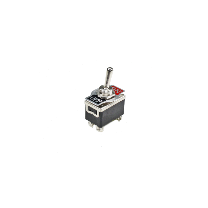
I thought using one of these
http://www.musikding.de/bilder/produkte/gross/Kippschalter-DPDT-2x-UM-robust.jpg in this case the reverb circuit will get voltage running once the whole unit is plugged yes ? the switch will only control if the signal flows to the reverb circuit or goes to output straight after teh Fuzz War and skip it... In that case I a m a bit lost though where to I connect the 6 legs of a DPDT ? |
Re: Combining effects (3 in one)
|
Yes. This is how pedals work for the most part- the voltage is always applied and what's switched is the signal path.
Lugs 1 and 5: jumper Lug 2: Input tip Lug 3: Effect input Lug 4: Effect output Lug 5: Output tip is the simplest way to do it.
Through all the worry and pain we move on
|
|
In reply to this post by Tune Tone
actually this is the one which is would be sweeeeet to do it with.. its a DPST... also possible I guess ?
the OFF row - lug 1 - the output of the Fuzz War's 3pdt log 2 - to the output jack the ON row - lug 1 to the Reverb circuits IN lug 2 to Reverb Circuit out correct ?? still learning.. every help and a tip is blessed! 
|
|
any clue on this one then ?
In the last message I included a photo of the desired switch I want to use for the reverb baypassing switch.. can it be true bypass with this one at all ? |
|
No, that won't work. When switched to 'on' you'll get what you want (signal goes from Fuzz War to reverb to output), but when switched to 'off' you'll get no signal at all. You need a DPDT, not a DPST.
Look at the offboard wiring page and try to understand how the switching works. Trace the connections for each position of the switch. Here's some reading if you don't understand the internal connections of different kinds of switches. |
|
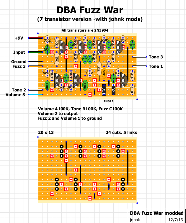
I counted 25 cuts in this layout.. is there an extra cut that shouldnt be there ? or just a false counting of the creator of this layout ?
cheers! A. 
|
«
Return to Open Chat
|
1 view|%1 views
| Free forum by Nabble | Edit this page |

