Custom Voodoo Labs Pedal Power 2 Plus

classic Classic list List threaded Threaded
82 messages Options
12345
Reply | Threaded
Open this post in threaded view
|

Re: Custom Voodoo Labs Pedal Power 2 Plus

Heath
Induction,

You're right, I had no idea the color of the end of a component meant anything, especially when you can only see one end.

Be that as it may, the description says:
"D1 - Diode on the far left is 1N400x, try 1N4001 is for inline polarity protection.  Negative on A rail, positive on B rail"

I'm not intending to be argumentative, but that's incorrect.  Unless Anode = Negative and Cathode = Positive on some diodes.  Anyone else building this would either build it non-working or be smarter than me and realize sending your voltage into the cathode of a diode is not going to work and build it right regardless of the description error.  


Rocket88,

Again, thank you for this layout.  I certainly couldn't have come up with this on my own and I now have an awesome working power supply due to your work and efforts.  Any feedback from me is only in the spirit of community and is in no way mean to reflect negatively on your skills or intellectual property.  :)
Reply | Threaded
Open this post in threaded view
|

Re: Custom Voodoo Labs Pedal Power 2 Plus

rocket88
Administrator
heath, no worries man, i'm not even thinking you're being argumentative nor do i think anyone else is. for some reason it seems as though everyone is on pins and needles with what they say here lately. to clear up any confusion i updated the layout changing the words "positive" and "negative" with "anode" and "cathode."

btw, good catch on the written description, someone asked for it and i put it in, i didn't read what i wrote carefully before posting it, so thanks buddy.
Reply | Threaded
Open this post in threaded view
|

Re: Custom Voodoo Labs Pedal Power 2 Plus

induction
In reply to this post by Heath
Heath wrote
I'm not intending to be argumentative, but that's incorrect.  Unless Anode = Negative and Cathode = Positive on some diodes.  Anyone else building this would either build it non-working or be smarter than me and realize sending your voltage into the cathode of a diode is not going to work and build it right regardless of the description error.  
I don't disagree, but I remember a conversation where someone explained to me why all of the polarized components in their circuit were reversed from what was in the schematic. I can't remember their explanation (I deleted it from my memory with extreme prejudice so it wouldn't corrupt my brain), but I remember that it made a certain kind of sense. What I took away from the conversation was that '+' and '-' can be misinterpreted, but 'anode' and 'cathode' can't.

The difference is that it is not always clear what the '+' and '-' refer to (is it the relative voltage?, or the direction of travel of the positive charge?, or the direction of travel of the electron?. Is it referring to the component leg, or to a node in the circuit, or to the way charge collects inside the component?). Electronic drafting conventions change over time and are inconsistent between different sources. (At one point, apparently, it was convention to arrange components in a schematic so that anodes were always on the left, which I can only imagine was disastrous.) It's not correct or incorrect unless you specify what you mean by it. On the other hand, 'anode' only means one thing.

When I make layouts for other people, I try to make them un-misinterpretable, but I usually fail. And when I don't, there's a typo.
Reply | Threaded
Open this post in threaded view
|

Re: Custom Voodoo Labs Pedal Power 2 Plus

iggy
hey guys thanks for clearing that up. I was a little confused as to the diode direction as well. but that just reflects my lack of knowledge. Got all my parts in and ready to start building. Until i realized the size and layout of the board. did you build this on vero? where did you get  a vero 31 tracks tall?   or did you just use a perf board and point to point wire it?

excited to build this bad boy.

thanks for your great work on this.
Reply | Threaded
Open this post in threaded view
|

Re: Custom Voodoo Labs Pedal Power 2 Plus

Heath
This post was updated on .
Heya, Iggy.

My perf is 30 tall.

I has a sort of blank strip at both ends, like in this picture:


So I just drilled an extra row of holes there, as needed.

As to 30 row vero, I get some fairly big-ass pieces off of Ebay.  Let me know if you want a link.


However, you will notice that Rocket88 was generous with his spacing, which is great for heatsinking the regulators.  You can very easily remove a few of those columns near the end and size it down if you need to.  I marked the rows that should have nothing connected to them with the weird red thermometer looking things in the pic below.  I considered doing this but since it was just one row and I am so ADD I'd probably forget the updated spacing, I went for drilling holes in that extra "row."


If you do decide to remove a row or two, I'd go sparingly as the extra space is nice to have.  You can also "stitch" two pieces together.  If you do so at the IC then the 8 pin socket could work pretty well for holding them together.  Also with the vertical alignment of the copper strips, this is even easier to do than normal.

That said, I HIGHLY recommend this layout.  Since this is to be a desktop recording power supply, I'm going to house it in one of the larger Tayda plastic enclosures and it should be good to go with plenty of room.  If I make a pedal board version, I'll probably use an aluminum enclosure.  

I'm powering mine with a 12volt 500mA wall wart that measures closer to 18 volts.  That's QUALITY!    
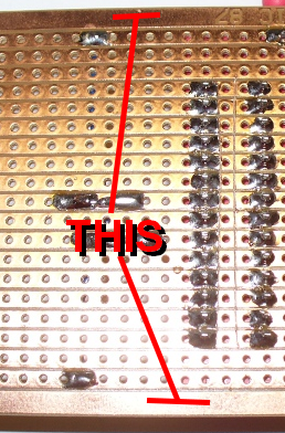
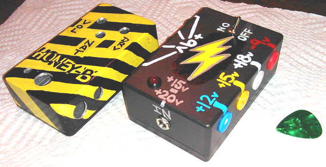
Of course this awesome circuit regulates all that.

I alos plan on building Induction's version as well and have it outputting -9v, 9v, 12v, 15v, and 18v.  I plan to power it with a 20v 1amp wall wart (plenty of amperage for those reverb pedals, etc.).  I figure between those two power supplies I can power any damn pedal!


One warning, though.  One of my cables that I made for it had a short, so when I plugged it in to the power supply it read 0 volts and the very last regulator in my ground chain got HOT.  I discovered this by burning the shit out of myself on it.  Thank goodness I had the recommended bolt and washers on it.  
Reply | Threaded
Open this post in threaded view
|

Re: Custom Voodoo Labs Pedal Power 2 Plus

rocket88
Administrator
 thanks buddy for the support and promotion of the power supply. like heath said you can cut out as many of the regulated +9V supplies are you want if you need it smaller. i really wanted it to have 6 +9V because i figured it would be enough for a "normal" pedalboard, and the occasional PNP device like a tonebender or Ge fuzzface, and an 18V supply for something that needs/could use the extra power for more headroom, but doesn't have an internal charge pump. the hope was that you don't need to have a lot of daisy chain wires, like what comes with the onespot. in fact for me i'm trying to find an enclosure that i could put 2 of these in so i could power my whole pedalboard.
Reply | Threaded
Open this post in threaded view
|

Re: Custom Voodoo Labs Pedal Power 2 Plus

iggy
In reply to this post by Heath
Heath thanks for info. One more part order and I'll be all set. be so nice to have a descent power supply. since my current stuff is embarrassing. and noisy i'm sure. So thanks to all that have worked on this project, very useful item for all here.
Reply | Threaded
Open this post in threaded view
|

Re: Custom Voodoo Labs Pedal Power 2 Plus

Heath
In reply to this post by rocket88
I bet this would do it!  


Hammod-style 4S1032L Looper


Also the larger plastic enclosure from Tayda might be a good idea.  You could probably fit 2 of these side by side (or maybe both of them on edge!) and take the center outs to the side and run them in a sort of zigzag...  I bet you could get at least 6 on a side.

A 1amp supply with 2 1N4001 diodes at the gates would probably be more than enough to run 2 of these circuits.  Now THAT'S some power!
Reply | Threaded
Open this post in threaded view
|

Re: Custom Voodoo Labs Pedal Power 2 Plus

rocket88
Administrator
hmmm, not a bad idea, i definitely want to have a metal box, and the mammoth might work cause i can keep them all on one side. i was thinking about making a tall sheet metal one so i can have them staked, so the ports will be stacked and the 2 18V and 2 -9V will be on top of each other to prevent any confusion. or i had the idea of having one box standing up so the ports would be on the face of the box, if you know what i mean. i'm not sure though if i can get away with a 12V supply coming in for all 16 ports.

funny thing is i went into guitarcenter today to see if they had a 12V wall wart, and they asked me what it was for and i told them that i build a power brick and they kept asking who the manufacturer is because the plugs can be specific. they couldn't understand why i didn't buy one, and that i built the brick. some people just don't get it.

even funnier, i built a pedal for a local musician that was there testing some new basses with the pedal while i was there, total coincidence, and they kept asking who built it and when he saw me he just pointed. they had him open it up for the serial number and showed them my signature, they were baffled.
Reply | Threaded
Open this post in threaded view
|

Re: Custom Voodoo Labs Pedal Power 2 Plus

Heath
I'm posting a layout of what I am currently using.  This first build is specifically for using at my desk for testing pedal builds, recording at my workstation, etc. so it's not specifically built for pedal board use, but it could be, if housed in a sturdy enclosure.  I'm just not sure if a normal pedal board would need -9v, +9v, +12v, +15v, +18v supplies.

(Disclaimer, this is Rocket88's layout.  I have changed a few values for my own use and am publishing it here for others who might find the changes useful.  As far as I know, all credit for this circuit goes to Rockedt88 and Induction).


Additional info:

- I had what is marked as a 12v 500mA wall wart to use with the original design.  Turns out the wart produces closer to 17.5v which was lucky for me because it is perfect for this modified circuit.

- The wire that says "other side" simply means that I recommend physically placing that output jack on the other side so that there are 4 on each side.

- I replaced the 2 9v regulators at the top left of the layout.  First one is a 7812 and the second one is a 7815.  This gives 4 +9v outs on one side and the other side has +12v, +15v, +18, and -9v

That's pretty much it.  Not much you can't power with this puppy.  Just make sure you label those jacks! :p  I'm pretty sure this will fit perfectly in a Tayda small black plastic enclosure.  I'll be trying that tomorrow.

Rocket88, Induction, if you see anything there that might make this thing explode or something, let me know, heh!
Reply | Threaded
Open this post in threaded view
|

Re: Custom Voodoo Labs Pedal Power 2 Plus

rocket88
Administrator
looks good to me. the changes you made are nice ones. i didn't think about doing that figuring any pedal that needs 12V or 15V would have an internal charge pump. i don't think anything will explode man, good freaking job buddy
Reply | Threaded
Open this post in threaded view
|

Re: Custom Voodoo Labs Pedal Power 2 Plus

Heath
I've had this built for a little while but forgot to post a picture.  

Here is my 9v/12v/15v/18v/-9v regulated pedal building workspace/recording desk power supply (with a 1590B enclosure and guitar pick for size comparison):


I built this in an ABS plastic enclosure from Tayda (the small one).  The 9v side are all black jacks.  On the "assorted" side I used colors as a bit of a visual stimuli to reduce the risk of plugging into the wrong voltage.  I also think it looks cool (opinions WILL vary :p ).

For the record, I've found several uses for 12v and 15v supplies.  The Pork Barrel and Current Lover from Madbean both benefit from 12-15v.  The Boobtube prefers 12v.  The Clone Theory likes 15v.  Of course in all of those scenarios you could include a charge pump.  I don't mind doing that in some cases, but I don't really like sticking charge pump daughter boards and, in many cases, toggles to switch voltage in half of the pedals I build.  I find this to be a convenient alternative.  

I also ended up including an ON/OFF toggle (which I would probably omit in a Pedalboard power supply) because I just didn't want 8 live outputs sitting on my desk, but I also wanted to have it ready to use at a moment's notice.  

So... no more (or at least a lot less) 9v batteries cluttering up the place with random charges left.  
Reply | Threaded
Open this post in threaded view
|

Re: Custom Voodoo Labs Pedal Power 2 Plus

rocket88
Administrator
Reply | Threaded
Open this post in threaded view
|

Re: Custom Voodoo Labs Pedal Power 2 Plus

kirshman
I just built this thing with a 12 v wall wart.  my jacks are only getting to 8.92v though.  Is that enough?
Reply | Threaded
Open this post in threaded view
|

Re: Custom Voodoo Labs Pedal Power 2 Plus

rocket88
Administrator
Reply | Threaded
Open this post in threaded view
|

Re: Custom Voodoo Labs Pedal Power 2 Plus

eldredracing
Where are you guys getting the male to male cables to use with this supply? I can't find them anywhere.  Thanks for the layout, the power supply works great.
Reply | Threaded
Open this post in threaded view
|

Re: Custom Voodoo Labs Pedal Power 2 Plus

Heath
This post was updated on .
I ordered a bunch of the jacks off of Ebay (2.1mm DC barrel) that have about 6-8 inches of wire connected to them.  Stick two together and you got your cable.  They are pretty cheap and you get to control how long you want them.
Reply | Threaded
Open this post in threaded view
|

Re: Custom Voodoo Labs Pedal Power 2 Plus

Heath
In reply to this post by eldredracing
Reply | Threaded
Open this post in threaded view
|

Re: Custom Voodoo Labs Pedal Power 2 Plus

tabbycat
hey rocket88, thanks for layout, it looks great. will definitely build one of these. maybe two or three.

thanks to this site it seems i'm forever one power jack and one patch cable short of a set up.
Reply | Threaded
Open this post in threaded view
|

Re: Custom Voodoo Labs Pedal Power 2 Plus

tabbycat
hey rocket and induction, just a note to tell you that i posted a link to this collaborative byo psu layout at fsb with a link to this thread. as i know you are both members there too, and i linked it to here, i hope that's ok with you. http://freestompboxes.org/viewtopic.php?f=28&t=26514&p=252407#p252390

ice-9 there is working on a psu design and looking for ideas/inspiration/etc. maybe you could cook something up in collaboration? he can do the cad thing so it could go full-on pcb.
12345