Custom Voodoo Labs Pedal Power 2 Plus
12345


12345
|
Administrator
|
cool man, it's all good. that's not a bad idea. i'll have to do a little more reading about making an isolated PSU, from what i've read they typically end up bigger then stompbox size, but there has to be a way to get it small enough.
|
Re: Custom Voodoo Labs Pedal Power 2 Plus
|
In reply to this post by Heath
Thanks for the cable sources. After building amps and pedals, surely I can handle soldering two wires together.
|
Re: Custom Voodoo Labs Pedal Power 2 Plus
|
In reply to this post by rocket88
great work. i really could use this. everytime i get close to buying one of these i just buy something elsre. i have always just used a daisy chain. never had any problems .thanks. what 12 volt power supply do you reccommend and how many micro amps?
|
|
Administrator
|
|
This post was updated on .
Just thought i would add this link to a good cheap power supply with interchangeable heads http://www.ebay.co.uk/itm/370897337707?_trksid=p2060353.m2749.l2649&ssPageName=STRK%3AMEBIDX%3AIT. If the heads are reversed you get a -ve supply and you can choose between 3, 4.5, 5, 6, 7.5, 9 and 12v. I bought one to use on my Reagun chorus as it has a weird 3.5mm powered audio jack type connection like my Moog. Measured the various settings to see how accurate it is clicking between settings and its spot on. I may buy a couple more of these but I am definitely going to build this power brick, its just what i need. At the moment i have 45 pedals powered by one plug and i am starting to get a big sag in voltage towards the end of the chain which i presume you would expect.
Thanks Rocket and Induction  . .
EDIT: Obviously that power supply isn't going to be relevent to anyone outside the UK unless you have an adapter.
"Red velvet lines the black box"
|
|
This post was updated on .
Just building this and realised i have only 5 LM809s. Is it possible to swap one of the LM809s for a LM815 or LM812 which would give me this choice instead or do i have to up the incoming voltage?
EDIT: Just also realised my electro caps are only 16v apart from my 10uF. I can see a problem here. Could this be dangerous near the 18v outage?
"Red velvet lines the black box"
|
|
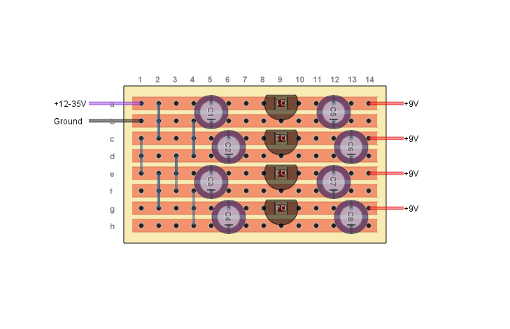
The supply voltage must be about 3V higher than the regulator output. So you can use a 7815 if you have an 18VDC adapter to power it with, or you can use a 7812 with a 15VDC adapter.
Be aware that amount of heat produced by a regulator depends on both current consumption and voltage drop, so if you use an 18V input source, it's very important to heat sink your 7809's. Also, are they really LM809's? Those aren't voltage regulators, they're microprocessor reset circuits. You want LM7809, LM7812, etc. (The LM prefix isn't crucial, so 7809 or L7809's or some other variation is fine.) You can use 78L09 instead if you won't use more than 100 mA from each regulator. |
|
In reply to this post by Hozy31
Yes, that will be a problem. The caps near the charge pump should be rated for at least 24V. If you increase the input voltage, then the filter caps on the input voltage (top left on the layout) also have to be rated higher than your input voltage. In general, I recommend using electrolytics rated for at least twice the voltage you expect them to see. |
|
Ok, Thanks so much for the info. Thought i was running up against a problem there. And sorry i do mean LM7809s just a typo. This is my first build that doesn't use 9v so have always bought 16v electro caps because they were slightly cheaper and generally smaller. This might also suggest why i have a couple of Madbean builds in the dodgy pile recently. Lesson learnt.
"Red velvet lines the black box"
|
|
Administrator
|
just to tag onto what induction said about the cap voltages. if you run too much voltage through them they will explode, literally explode. aside from being dangerous, it stinks. just a little suggestion is get the largest voltage caps you can with the smallest footprint. for this reason all my electrolytic caps are 50V caps, and the vast majority are from tayda. with voltage that high i NEVER have to worry about the voltage rating, since the odds of having a pedal that takes 50V is pretty much never.
|
|
Thanks Rocket. Definitely don't want exploding caps. Have ordered 50v ones.
"Red velvet lines the black box"
|
RE: Custom Voodoo Labs Pedal Power 2 Plus
|
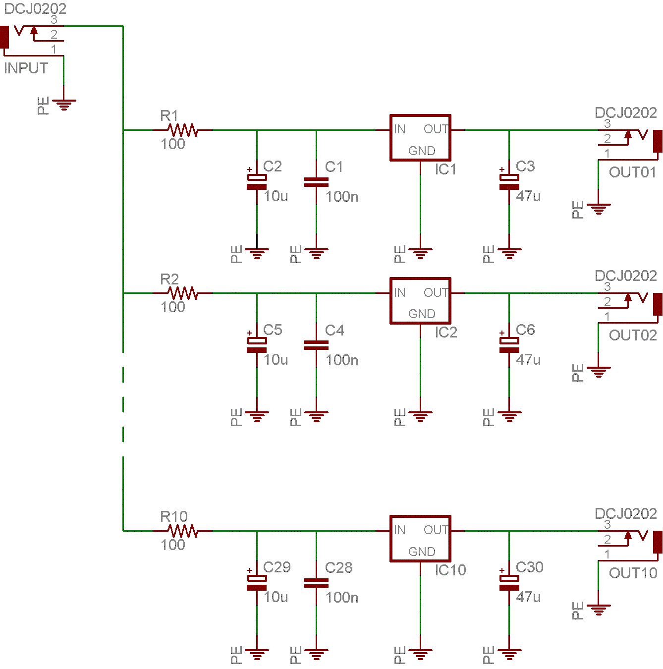
How about a schem on this. I suck at converting Vero to schem. Would love to do a PCB
But will look back to see if by chance one was added.
Yeah, 220, 221. Whatever it takes.
|
|
It's based on this, but a bit modified:
- There's an extra filter cap on each output - the charge pump is reconfigured to give both voltage doubling and inversion - there's no sag feature (though you could easily add one without modding the vero, just add a pot) - there's no direct output for the source voltage (the idea is to get clean, regulated power from a cheap, noisy adapter, so I saw no need to include an output tap for the supply rail. Again, you can add one without modding the vero.) |
RE: Custom Voodoo Labs Pedal Power 2 Plus
|
i used to have the first layout Zach posted on this threat for about a year now..
after having hum problems with some pedals i thought i should build something with more filtering.i've found "medusa" this is a really good clean supply i've forgot to post it though... verified  
|
RE: Custom Voodoo Labs Pedal Power 2 Plus
|
Whoot! From: [hidden email] Sent: 7/31/2015 11:32 AM To: [hidden email] Subject: RE: Custom Voodoo Labs Pedal Power 2 Plus after having hum problems with some pedals i thought i should build something with more filtering.i've found "medusa" this is a really good clean supply i've forgot to post it though... verified  
If you reply to this email, your message will be added to the discussion below:
http://guitar-fx-layouts.42897.x6.nabble.com/Custom-Voodoo-Labs-Pedal-Power-2-Plus-tp8192p23125.html
To start a new topic under Layouts, email [hidden email]
To unsubscribe from Guitar FX Layouts, click here. NAML
Yeah, 220, 221. Whatever it takes.
|
|
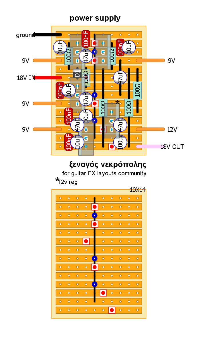
In reply to this post by ξεναγος νεκροπολης
Nice one Savvas, so nice and compact!
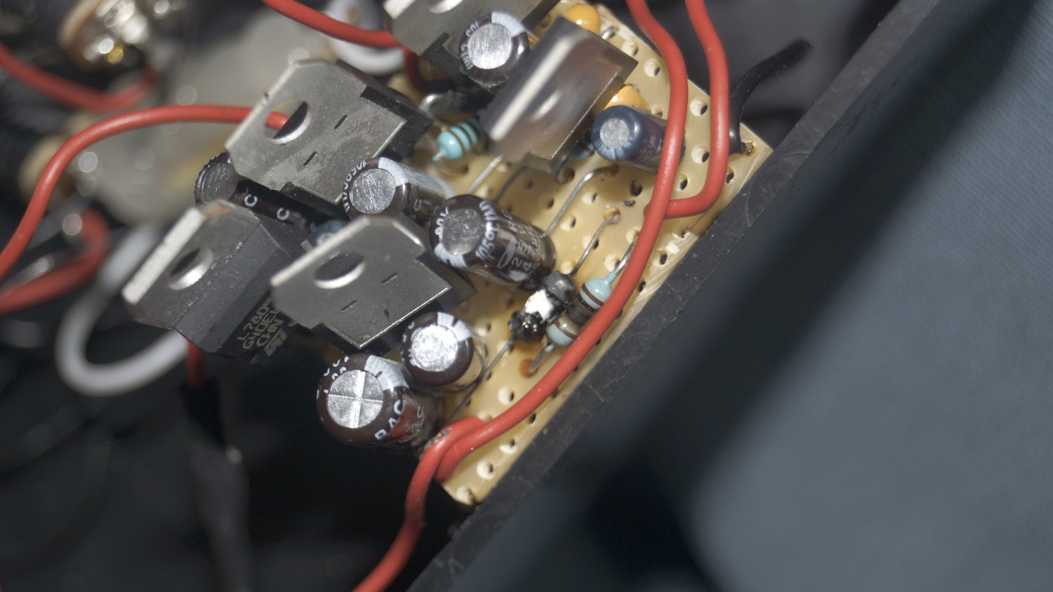
May have to build this as well now my LM7809s have been delivered. Did you add more heat sink to the regulators? Thanks
"Red velvet lines the black box"
|
Re: Custom Voodoo Labs Pedal Power 2 Plus
|
In reply to this post by rocket88
I just read this on the Topopiccione website
Is this a major concern? Should 1 Watt resistors be used with this layout? How big of a concern is heat in a layout like this? What is the essential difference between these two? I noticed the extra resistor and larger input capacitors. I have built the original Voodoo clone design and haven't noticed anything significant (I did heat sink each 7809) Although I did still find the supply a little noisy. Also, what about the use of the 78L09, I don't believe it is possible to heatsink the small SI packages easily. How much heat would something like this generate in that? I also found this design online, and I quite like it because it is a little more modular the divisions between regulator stages are a bit easier to pick out. 
|
Re: Custom Voodoo Labs Pedal Power 2 Plus
|
+1 on this warning
i 've just build a second one using the layout i posted above. a friend of mine gave me an old laptop supply and asked me if i could build a brick for him. i did it, and when i connected the board with the supply, smoke came out of resistors and regulators. i've used 1/4 resistors, as i did with mine. so.....i opened mine which works fine(is it?) and guess what...  burned resistors.. so my questions are. is it possible that resistors after burned out become something like links? is that why it "works"? using 1 watt resistors could solve the problem? |
|
This post was updated on .
In reply to this post by ξεναγος νεκροπολης
Danger, danger Will Robinson!
Using 1 Watt resistors would probably stop the resistors from burning out. However, it might just move the problem on to somewhere else in the circuit, causing something else to burn out instead. Solve one problem, only to create another. I think someone who really knows what they are doing needs to sit down with a calculator, and work out all the figures for voltage, resistance and current load in this circuit. Could a program like LT Spice do these calculations? Otherwise anyone building this is literally playing with fire. Maybe this layout needs to pulled from the site before someone has a horrible accident? |
«
Return to Utility Boxes - Blend, Power, Looper, etc.
|
1 view|%1 views
| Free forum by Nabble | Edit this page |

