Custom Voodoo Labs Pedal Power 2 Plus
12345
12345
|
Administrator
|
This post was updated on .
Figured I would post something I was working on with the help of induction.
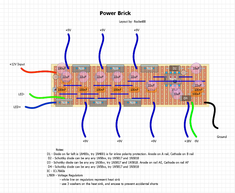
This is power brick, similar to the Voodoo Labs Pedal Power 2 plus, but with a few nice changes. It runs on +12V, and has 6 +9V outputs, 1 +18V output, and 1 -9V output, so a total of 8 outputs. With this you can daisy chain a -9V PNP pedal with your other +9V NPN pedals.  It's a little big, at 36x9 with only 4 cuts, 14 links, and 1 double link. |
|
Administrator
|
I didn't realize that I said that this runs on +20V, as you can see in the layout It will actually run on +12V. So if you have built this or are planning on it, just follow the layout below, and use a +12V power supply.
|
|
In reply to this post by rocket88
Hey Rocket!
Is this verified? I'm really interested in putting something like this together soon. |
|
Administrator
|
yea, i made one for a buddy, and it worked without a hitch. i still have to make one for myself though.
|
|
Great! Thanks man!
|
|
In reply to this post by rocket88
that lloks like something i need. do you have any other documentation on it? its a little hard for me to see all that=s going on. and how do you handle the outputs? do you have a separate ground rail for the output cables? and what are the 809's? haven't seen that part number before.
seems as there is something missing, but i'm not bright enough to know what. |
|
Neat! The 7809 is a voltage regulator, and they're pretty inexpensive on eBay:
7809 voltage regulators on eBay The 7660 is the ICL7660SCPA chip, I presume?? This unit could be put together for under $40 including the enclosure and 12V power supply. I assume the power supply should be 1 amp or better? |
|
Administrator
|
frank - yea its a 7660s. this was the first layout i made so it's not the neatest. i'll redo it in the am, i'm a little too out of it at 3am my time to it right. i just used a 12V power supply from radioshack i had laying around, i'll have to check what i gave my buddy and get back to you, but i think 1amp should be fine. it cost me like maybe $15 to put it all together including the enclosure. if you figure an enclosure it $5, the chip is like $0.50 max, the regulators are like $5, plus the wire and odds and ends.
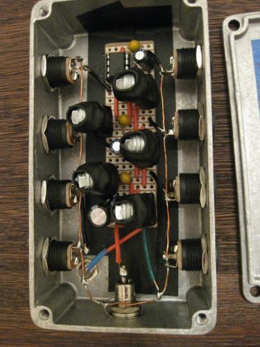
iggy - what documentation do you mean? this way i make sure when i redo the layout i don't miss anything. also the grounds are all connected between each jack, and a one jack is also connected to the board at ground. the 7809 is a power regulator, if you look on ebay or tayda for L7809 and you'll find them, also frank posted a link to ebay for them from tayda. you just have to remember that there is a heatsink on top of the regulator, hopefully induction doesn't mind, but he helped me design this and is similar to one he has made, look below to see the wiring and how to handle the heatsink look at what he has done. the only difference in the one i built is that i used all the same jacks, but for mine i'm going to change it and do what he did.  here's what induction said he did for the heatsink: "Finally, notice that each regulator has a heat sink made of three small washers. The washer size was selected for maximum contact with the regulator tab, and there is thermal compound at each mating surface. The tab of each regulator is shorted to the ground leg, so I heat-shrinked each of the regulators as a precaution against accidental shorts." better to hear it from the person who taught me, then me try to explain it and make a mess of it all. lol |
|
It's a pretty nice project, but I would not say it is comparable to a voodoo Labs Pedal Power 2 plus. The voodoo lab is transformer based, with isolated (floating) ground for each output, allowing you to plug any pedal into any outlet basically.
I guess this design is more like the fuel tank, that one basically uses the same scheme you use: one big transformer to go from 120V or 230V to 12V and then filtering and regulating the power. For you the transformer is external for the fuel tank it is internal to the brick. Also this causes both of your designs to have common grounds (except of course for the 18V and -9V section on your design). All that is not to say this isn't a great design, just saying there is a reason the voodoo PP2 + is probably more popular then the fuel tank due to a different (dare I say better) design. In the end you just prevent more ground loops with the PP2+, that usually does not matter too much though...
My heart can go where my head can't fit.
|
That's correct, this is not based on the Voodoo Labs PP2. It's actually loosely based the AMZ power supply, which is itself based on several datasheet circuits in parallel. See the above links and this thread. |
|
Administrator
|
This post was updated on .
In reply to this post by MrTondo
correct mrtondo as i said it was made based on a custom power supply listed as a custom voodoo labs 2 power supply i saw on ebay, i'm not saying this is the same as the voodoo labs pedal. what makes the voodoo different is that it has isolated grounds, as you said. there are schematics online to that you can use to make one, R.G. Keen's Spider comes to mind. the problem with using internal internal transformers is the size of the enclosure you need to hold all of them. i've seen a few people that have build power supplys with internal transformers the put them outside the enclosure for space.
it is thought that having isolated grounds will prevent any hum, where having shared grounds will allow hum due to the grounds being daisy chained and the circuits being able to affect each other. induction, myself, and my buddy i built one for have not had any hum, and my buddy uses some monster gain pedals. edit: the layout above has been updated with information asked |
|
Ok that information helps. think i have a good enough idea of the circuit now to give it a try. I see al the grounds are daisy chained. how do you handle the -9 volt and 18 volt outputs. reverse the + & - on the -9 vlt connections? think i'll start putting together a parts order for this. thanks again. and thanks for updating the layout for me.
|
|
Administrator
|
i'm not sure i know what you mean iggy. just hook them up as normal to the + terminal of the jack. the 7660s chip converts the +9V to -9V and +18V, so the only think that's different is how much power you get from the output, not the wiring. i hope that makes sense, cause sometimes in my head things make sense, but to others it doesn't. lol
hey man, i'm glad to help. it's part of being in the community. we're all here to help each other, right? 
|
|
my mistake. forgot to factor in the 7660s chip working its magic in there. makes perfect sense now.
|
|
In reply to this post by rocket88
Rocket88, I just built this and, aside from 2 small issues, it's fantastic!
The 2 issues I had were with D1 and D3. By the description in the layout, they6 are backwards. The layout would seem to indicate Cathode left, anode right whereas mine had to be anode left, cathode right. With D1 per the layout I got no voltage through the diode. After reversing it (anode left, cathode right) all of my 9v leads were getting power perfectly. However, my 18v lead got strange fluctuating readings that eventually resembled watching a capacitor discharge. I swapped that one (again anode left, cathode right) and the 18v lead began producing the proper voltage. Very small issues for such a great layout, though. So THANK YOU regardless. I am digging it! |
|
Administrator
|
huh, i didn't have the problem. i'll go back and check the one i build for my buddy and see how i put the diodes in. i'll make the change to the layout. so just want to make sure i'm looking at the right things, it's d1 and d3, on the layout they're backwards form how they should be on the actual board?
also, glad it's working for you. i still have to build myself one. lol |
|
They are drawn correctly (the white band indicating the cathode is showing at the top of each standing diode), it's just the written description that's confusing.
|
|
In reply to this post by rocket88
Yep, it's the two standing 1n4001 diodes. You mention D1 as Neg on rail A and Pos on rail B. So unless I am just misinterpreting what you mean, it would need to be the Pos/Anode leg on the A rail (voltage in) and the Neg/Cathode leg on the B rail (voltage out to rest of the board).
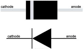
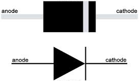
D3 was the same orientation description, so after probing the board when my 18v lead wasn't reading the correct voltage and running out of other ideas why, I took a shot and did the same thing, pulled the diode and reversed it. Works perfectly after that. ...and just to avoid any semantic issues, my understanding of the polarity of D1 and D3, according to the layout text, is this:  I changed D1 and D3 to the orientation below and everything works great: 
|
|
In reply to this post by induction
I honestly can't see any graphical indication on the standing diodes. Might be my eyes :( |
|
In DIYLC, the color of a standing diode shows its orientation. If the visible part of the diode is the color of the diode body (black, in this case) it indicates the anode. If the visible part is the color of the stripe (white, in this case) it indicates the cathode. These are white, indicating the cathode. This is all very obvious when you make the layout, and almost impossible to notice for anyone else, partially because the colors of the diode body and stripe can be anything you want them to be.
Rocket did a good job by adding a written description to avoid confusion, but the semantics of diode (and polarized cap) directions are easy to misinterpret. It's better to use the words 'anode' and 'cathode', but I admit that I often use '+' and '-' (when I remember to mark them at all). It's always a good idea to have a schematic available when when building, even if the layout is confirmed. In this case, the datasheet for the 7660S will clear up any confusion. |
«
Return to Utility Boxes - Blend, Power, Looper, etc.
|
1 view|%1 views
| Free forum by Nabble | Edit this page |

