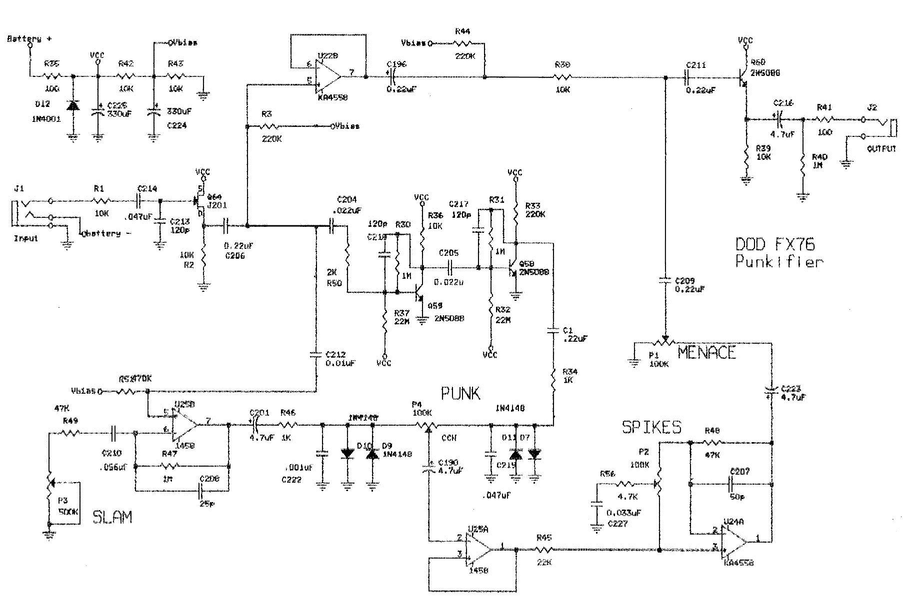
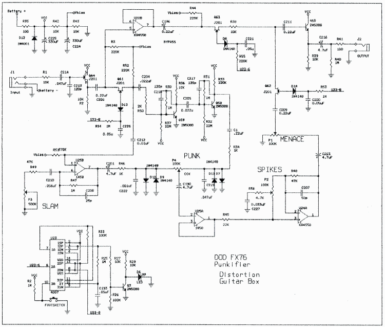
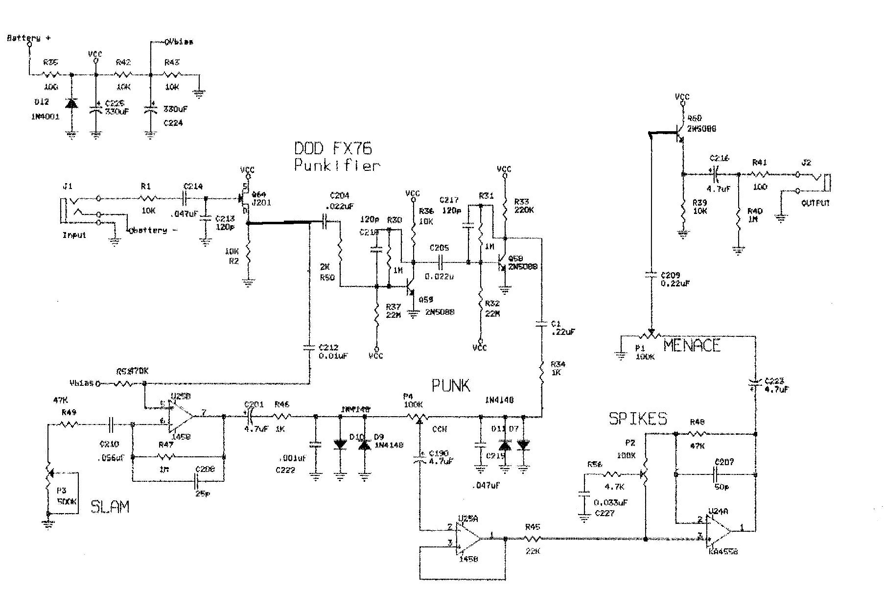
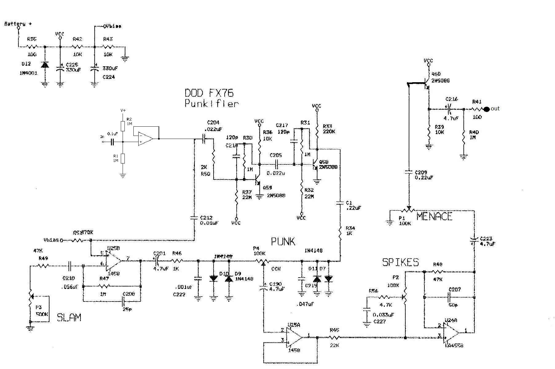
DOD FX76

classic Classic list List threaded Threaded
23 messages Options
12
Reply | Threaded
Open this post in threaded view
|

DOD FX76

Alex
Once again, I'm drawing a layout for this pedal.
I've removed the switching system.
Any possible comment or correction on this schematic would be appreciated


Original:
Reply | Threaded
Open this post in threaded view
|

Re: DOD FX76

Ciaran Haslett
I might be reading this wrong but...

Remove the In/Out buffer as its a straight up and down dirt box
Input at C204/C212
Output at Menace 2
U22B buffer and all connected to it are part of the bypass so it could go.
Unless its necessary to buffer Punk 2, U25A could probably go too (not so sure about that though as it's clearly part of the primary circuit)

I'd wait for someone else to chime in before you take my word on this one.
Reply | Threaded
Open this post in threaded view
|

Re: DOD FX76

mirosol
Administrator
In/out buffers don't hurt anyone. If you feel those are not taking too much space, then leave them in. They also serve as impedance transformers and make the circuit play nice with other pedals. Input buffer is quite important here, as it splits the signal for the two paths blended together later on.

Take the C212 from the input buffer J201's source and do the same with C204 - thus dropping the C206 completely. The U22B and all the components around it can go as those serve only as the bypass signal path. Also, drop the R39(?) and C211. Take the C209 straight to 5088s base.

The 22M resistors.. I'm fairly certain the sound will be close enough if you take two 10Ms in series instead of 22M which may be difficult to source.

Otherwise everything looks pretty good.
+m
fyaelectronics.com
Reply | Threaded
Open this post in threaded view
|

Re: DOD FX76

mirosol
Administrator
This post was updated on .
In reply to this post by Ciaran Haslett
And Cieran! Noooo!
The U25A inverts the signal for the tone control. Not removable.


So it could be like this:


I would probably drop the 10K from input and take a 1M from where it was to ground. And since it's me, i'd go with 1N5817 as series polarity protection too. And what goes for the pots, the Slam will definitely need to be C500K. Others should be fine as linear.


And one more thing! There's no path from the input buffer gate to ground, so the input buffer won't work as per the schematic. There needs to be a 1M or similar value in parallel with the 120p cap.
+m
fyaelectronics.com
Reply | Threaded
Open this post in threaded view
|

Re: DOD FX76

nocentelli
I'd agree you want the input buffer to.feed the parallel input: Why not use a quad IC, use the fourth for a simple non-inverting buffer for the input and leave off the output buffer? One IC and two transistors.
Reply | Threaded
Open this post in threaded view
|

Re: DOD FX76

Ciaran Haslett
In reply to this post by mirosol
Cool.  I couldn't work out what it was doing.  I spent too much time looking at what came before it that I ignored what came after.  Cheers lad
Reply | Threaded
Open this post in threaded view
|

Re: DOD FX76

mirosol
Administrator
In reply to this post by nocentelli
Nocentelli;
For some stupid reason i'm not confortable with dropping the output buffer :) I think the output impadance is one of the reasons why these circuits feel so stable and not flakey at all.

Quad opamp on the other hand is not a bad idea. Only 3 channels are used and replacing the input buffer with opamp would same us from using a ever-so-scarce JFET.

So. Something like this? A quad opamp and three common transistors.


+m

fyaelectronics.com
Reply | Threaded
Open this post in threaded view
|

Re: DOD FX76

nocentelli
Yep, or bias the input buffer with a 1M from the 10k||10k vref divider, save yourself a resistor and double the input impedance.
Reply | Threaded
Open this post in threaded view
|

Re: DOD FX76

mirosol
Administrator
That should work too..
+m
fyaelectronics.com
Reply | Threaded
Open this post in threaded view
|

Re: DOD FX76

Alex
Couldn't get it any smaller than this.
Does it look alright to you?
Reply | Threaded
Open this post in threaded view
|

Re: DOD FX76

mirosol
Administrator
Whoah! That's way smaller than i expected! I'll give it a go right now and report back in an hour...
+m
fyaelectronics.com
Reply | Threaded
Open this post in threaded view
|

Re: DOD FX76

Alex
Cool!
Reply | Threaded
Open this post in threaded view
|

Re: DOD FX76

nocentelli
21 x 21, good omen
Reply | Threaded
Open this post in threaded view
|

Re: DOD FX76

Alex
I've almost forgot to ask something on another subject:
On Bernardduur's Turkish Small Tone schematic, do you think the 220K at the input should be a trimmer or a pot? I assumed it changes the tone of the color switch, correct?
Reply | Threaded
Open this post in threaded view
|

Re: DOD FX76

mirosol
Administrator
In reply to this post by mirosol
I'm working on it, and i think i found an error in the schematic, which i should have seen in the beginning. Inverting buffer does not work as depicted in the schematic. I'll try to tweak my build accordingly...
+m
fyaelectronics.com
Reply | Threaded
Open this post in threaded view
|

Re: DOD FX76

mirosol
Administrator
Phuh. FucX the scum that  posts erroneus schematics online.

Ok. To begin with, i replaced the 22Ms with 2x10Ms in series. Did the job pretty well. Then i fired the circuit up and as expected, no signal. Probed it all the way to the U25As input. This part has an error. The inverting buffer does not work as depicted (http://hyperphysics.phy-astr.gsu.edu/hbase/electronic/buffer.html). I swapped the inputs by taking the link from pins 8 & 10 to 8 & 9 + taking the 4µ7 straight to pin 10 (the non-inverting input). This cured the buffer. At this point i noticed that the punk pot pins 1 and 3 are in reverse.

Next, the "spikes" aka the tone control. To me it looks like basic tone stack as we find in tubescreamer and the likes. Except the input is once again going to the wrong input of the opamp. Now, i'm hoping someone who knows how to fix this steps in and tells me if the tone is even possible to get working as in the schem? If not, then it should be fixed to look more like the TS tone control. This would mean taking the input to non-inverting pin and supplying this pin with VRef and a filter cap, as in TS. As it is, it works, yes. But it sounds very much glitchy and synthy when maxed. Not like the original. This is the part where we need help...

Then. The output buffer doesn't work as in our simplified schematic. It'll need some reference voltage. Two options, 1) take 1M resistor from supply to base. Or. 2) take 470K resistor from VRef to base. I did the latter with my board and it works.

Now this sounds.. Well. Not that far off from the original, but not close.

Anyone care to chip in with the tone control?
+m
fyaelectronics.com
Reply | Threaded
Open this post in threaded view
|

Re: DOD FX76

mirosol
Administrator
This post was updated on .
Slight update. I tried to add a 10K from VRef to pin 12. It did make the control better, but did not fix it.

I need to stop for today (been a long day), but i'll check the circuit again tomorrow evening.


Couldn't help myself and did some more investigating. The 33n in the tone section is actually 3n3, the 47K in the OD250-part is actually 4k7 etc etc. There's very little correct in that "schematic". :) Guess i'll start on real trace tommorrow.
+m
fyaelectronics.com
Reply | Threaded
Open this post in threaded view
|

Re: DOD FX76

Alex
Crap! Bloody fake scheamtics!
We've done it all for nothing.
Meant to happen once in a while.
Let me know if you manage to reverse your original to check the differences.
I'll draw another layout after
Reply | Threaded
Open this post in threaded view
|

Re: DOD FX76

mirosol
Administrator
I got the original right here. And due to sound being rather close, i think the topology may be correct.
+m
fyaelectronics.com
Reply | Threaded
Open this post in threaded view
|

Re: DOD FX76

Hozy31
Damn! I also built this last night but had to stop due to a migraine but all components are in. Miro could you list the changes you made so i can remedy my build. Ta.
"Red velvet lines the black box"
12