Debuggin a Strip Board (Heart Throb and Others)

Debuggin a Strip Board (Heart Throb and Others)

|
This doesnt pertain to any specific builds but advice or ideas would be appreciated.
The pictures below are for a Heart Throb Tremolo, that Ive built before but suddenly doesn't seem to be working for me when I build it in the way described below. So I decided I don't care what size enclosure my effects go in because I got tired of cutting boards down to size and then trying to figure out a secure way to mount them inside the enclosure that still allowed them to be easily removed for future repairs or mods. If someone wants a pedal from me, they are just going to have to make room for it on their board, if Im going through the trouble of making it for them for free im not going to spend extra time trying to figure out how to make an Avalanche Run fit into a 1590A sized enclosure to fit on their Pedal Train. So I decided to just build the layouts on an entire 94mm X 53mm strip board, so a layout that occupies 21 holes wide by 12 rows tall, would just be built in the center of the board taking up the same amount of holes and rows that the layout calls for, but would leave the remaining areas of the board (the unused portions) free to use for future modifications to the circuit. The extra rows on the upper and lower portions of the board shouldn't cause issues if there are no bridges or jumpers attached to them, but I was wondering if I should terminate the outer ends of the rows that the actual circuit it built on? Would these extra portions of the rows that are receiving current, but aren't connected to anything, be causing my effect to not work properly because power is being drawn away from the circuit? I tried building a effect that Ive built a bunch of times, using all the same components each time, with the only difference being that I didn't cut down the board to size. I just built it within the 21x12 dimensions on a full sized 94mm X 53mm strip board. I made sure the extra rails on the top and bottom were not attached to anything, and the effect doesn't work. Bypass works fine, but I get nothing when I turn it on. Currently working on a Heart Throb wherein I built it on a whole board and didn't terminate the outer ends of each row of the circuit. Last night it dawned on me as I was driving home that Ive eliminated every variable that could be causing faults except for the fact that I didn't cut the ends on the rows being used in the circuit. So My thought was that this may be causing the circuit to not work due to the fact that those rows are getting power, but the power can still continue on past the components in the circuit, instead of the flow of power only being isolated to the components on the board and bare minimum of rows required for them to function. I realized that essentially Ive got 12 wires just dangling off each side of the board that are powered but not completing a circuit. Heres some pics Component side minus wires: 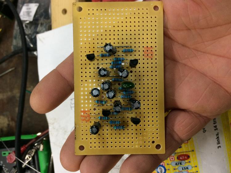 Bottom Side (soldered side minus wires):  Should I sever the rows like this because my effect isnt working:  Ive checked ALL the components, rebuilt numerous times, (I work in an electronics components shop so I never run out of supplies), Ive reflowed the solder points, I use a small jewelers saw to cut between the rails to eliminate bridges, washed the boards with Isopropyl Alcohol and a brush, Tested every cap with my cap tester (polarized tester for electrolytic and non polarized tester for poly film), tested every resistor value before mounting them, (Im dyslexic so I have to check each component multiple times before I mount them) Im going to sever the excess portions of the rails to see what happens while waiting to hear back from anyone on the forum. Thanks in advance for any advice and guidance.
make them loud enough to melt the sun
|
|
|
There's no reason why having your layout on the larger board should cause any problems. The only thing I can think off beyond the normal build issues would be that the board could ground out on the enclosure if it touches the sides (being larger than normal). I'd think that your issues were more to do with normal build problems, mis-placed parts / links / cuts, wrong component values, solder bridges etc etc. Have you been through the layout with a multimeter or an audio probe? |
Re: Debuggin a Strip Board (Heart Throb and Others)
|
|
I have been through it with a multimeter but Im not sure what the values should be and where, I used to just build them the same way and they always worked. Never used an audio probe.
make them loud enough to melt the sun
|
|
|
Looking around the forum this isnt the first time you've had issues with the heart throb. Did you solve the problems you had in the past or is this the same build? I'd recommend making an audio probe, there should be a link somewhere on the forum. Not only is it a really useful tool for debugging problem circuits but it also gives you some insight into how the vero layout works and the way the signal path runs through the components. |
Re: Debuggin a Strip Board (Heart Throb and Others)
|
|
The last time my issue was the 220ohm resistor. I kept putting in a 220K Ohm. i swapped the 220K for a 220 and the first heart throb worked great, so have all the others ive done, this one is just giving me the damnedest time. I made an audio probe and took just the board and connected up the 9v and Ground, attached the ground of the probe and started poking around and I get the same sound from every component, sort of a high speed tremolo effect on a drone, I havent attached the pots or switch yet to see if that has any effect on it.
make them loud enough to melt the sun
|
|
|
You need to have an audio signal....... the clue is in the name :) What you are hearing with the probe is the 9v supply. hook up the input to a jack and plug in your guitar, give it a strum. you should be able to follow the audio signal through the circuit following the vero layout and a schematic if you have it. try to find a place where the signal goes dead and you should get a good clue where your problem lies. I'll see if i can find a something to help you out. |
|
|
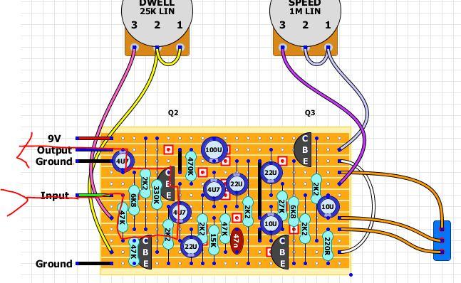
 Right, i'm going to take a punt on my understanding of this, i'm prepared to be very wrong. The signal path seems to be fairly small, travelling from the Input across the 47K (R1) and 4u7 cap (C1) and into the Base of Q2, out of the collector of Q2, through another 4uf cap (C4) to the output. I think that the rest of the circuit forms the oscillator which modulates the volume through Q1. I suspect that if you put the probe or meter on that part of the circuit you will just get the hum from the supply. I am no expert on this by any stretch so i'd perhaps see if anyone else can verify what i've just said. I'd think that you will need the pots and switch connected, if they arent i think you should still get a clean, unmodulated signal to the output but i may be wrong. |
|
|
|
Re: Debuggin a Strip Board (Heart Throb and Others)
|
|
You Rock so hard. Thanks a bunch. Im going to try all this today. The one thing I realized that Ive done differently on this build is that the 100u Electrolitic is 16v instead of 50v, but I figured that wouldnt be an issue since im only supplying 9 volts so 16 should be more than enough right?
Also Im using one of these which I use in all my builds: 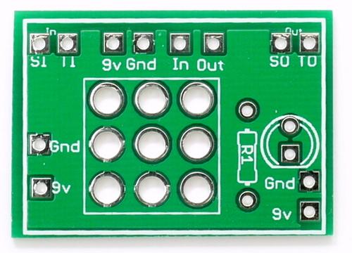 And I wire it based on their diagram: 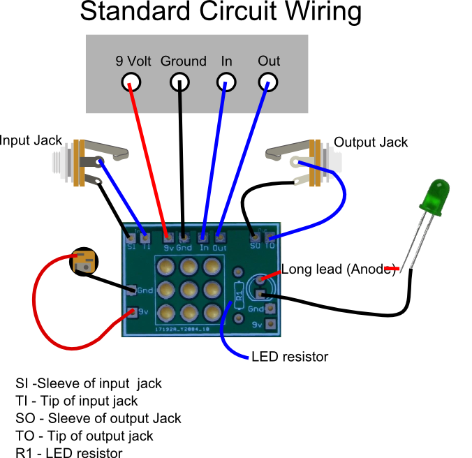 I made a bunch of the heart throbs like a year ago for friends, but i cant remember where on the foot switch PCB I connected the second ground connection. Also wouldn't I just be able to use a jumper to connect the 2 ground connections on the strip board to one another so that i would only need to make one ground connection from the strip board to the PCB? Similar to the jumper at Q3 E to Q4 B, or does the (bottom row ) ground signal need to travel through Q1 E and the 47K resistor and the rest of the circuit on its way to the SPDT toggle? You are seriously awesome for helping me with all this, I need to start keeping notes for all my builds so if I ever go back to them and make them again, I have a reference point. I started doing that with the fuzz pedals i make that Ive based off of multiple layouts, like which caps i switched to, what values of pots i use, and that kind of thing. This is all just stuff im doing, learning and making stuff for friends because I can't play guitar anymore. I didn't think I would be making the Heart Throb again, but my buddy wanted one. The others were so easy when I made them before once I realised the 220 Ohm resistor wasn't a 220K Ohm. The R in the layout looks like a K to me. :)
make them loud enough to melt the sun
|
|
|
The electrolytic cap should be OK, I think the rule of thumb is twice the circuit voltage but I think it'll be ok. It's not a problem to use caps rated much higher than your voltage, other than the size restraints of higher rated caps. The daughter board should be fine so long as everything is connected properly. And yes, use a jumper to connect the grounds, or solder one onto the ground lug of one of your jacks. As long as it is connected to ground somewhere it will be fine. Happy to help, I knew nothing 12 months ago and the folks here helped me out, glad to be able to give something back. |
|
|
In reply to this post by Peter Venkman
1) I haven't seen anywhere where you've stated you currently have this mounted in an enclosure yet, but if you do and it was painted on both sides, make sure you buff-off the inside paint around your input/output jacks so you can get grounding on the washers, etc. Typically grounding issues are your #1 culprit of problems. whether there, from the 9v input, etc.
2) As for an audio probe, do a lookup for a quick / cheap audio probe build .Off the top of my head I think I used an alligator clip, two wires with one already having a 1/8 male jack, a resistor, a short thick piece of solid wire or a nail, and some electric tape / shrink wrap. For input to the pedal I use a small male to male audio cord with a 1/8 to 1/4" adapter on one end to have the input coming from an iPod so that there is a constant flow of sound through the board (versus strumming a guitar), and plug it into the IN jack. (HINT: I also pick a song that I am very familiar with so that I know the QUALITY of the sound). My DIY audio probe is grounded to the pedal via the alligator clip side (usually to output jack ground), and the output wire from probe goes into an amp or other speaker. I start probing the solder points in the order signal should be going through the circuit. Once it stops or significantly changes quality or volume, I know that's a likely trouble area. An audio probe is a very useful tool, and is quick and easy to make. I don't know how I would find the gremlins without one. |
Re: Debuggin a Strip Board (Heart Throb and Others)
|
|
i dont use painted enclosures but i will scuff the surface around the mounting holes with a dremel with a wire brush head on it and try mounting it inside the box. the 9v jacks im using are these
 the barrel is plastic and the nut doesn't make any contact with the power supply or ground, but ill scuff up the area around those holes too. I sort of gave up after building it over and over and decided to try the Schaller. I know everyone keeps telling me to build the circuit on a bread board first but I get like 100 of these 19 hole by 34 hole strip boards through my job for like $2. Im trying to improve my soldering abilities and my dyslexia by just going straight from layout to board. It helps me understand the signal flow more easily because of my fucked up brain. When I look at the layouts not only do i see all the words and numbers all scrambled but the hole markings and the spacing between the rows (the lines in the picture) through me off. I kept building a board that was supposed to be 12X7 as 7X21 and I kept making it vertically until a 12 year old checked my work for me. Thats what my little apprentice dude does, he goes over the layouts I want to make, marks where the track cuts should go in red sharpie, and where the links go in blue sharpie on the actual board and then double checks them after I mark the cuts in black sharpie, then if they are in the right places, he has me cut the tracks and then checks again for me. He also goes over the layouts, enlarges them and prints them on 11X17 paper for me, and then double checks the components after I mount them, then gives me the okay to solder. Then he cleans the gaps between the rails and makes sure the termination cuts are cleaned out before we add the wiring. Im still trying to figure out what im doing wrong with this audio probe I built. 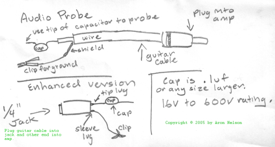 I made the top one in the picture not the enhanced version with the 1/4 inch input jack. I've tried clipping the ground to the output ground, the 9v ground, the footswitch pcb ground points, and im getting nothing anywhere on this board and even boards that I know work. I just get a low humming sound, like a Moog Squarewave drone. On the schaller im trying to build to get my mind of the hearthrob, I caved and went back to socketing my transistors, even though all the ones I've pulled from my heartthrob builds still test perfect on my NPN checker on my multimeter. Tried switching the 2N5088s for MPSA18s and still get nothing from the boards. This one just has me lost. The DBA Reverberation machine didn't give me as much trouble as this damn heartthrob and im building it the same way as all the other heartthrobs i built before. Testing components before mounting and everything. Im even working of pictures of the guts from previous heartthrob builds and im doing everything the same way. The only reason Im attempting the Schaller now is to take my mind of the heartthrob layout for a bit and because if i get it working I can put it in the same 2 pot, 1 toggle enclosure i already drilled for the heartthrob. again thanks in advance for the advice and any tips. sorry for grammatical errors, i am still using voice to text to type.
make them loud enough to melt the sun
|
«
Return to Debugging
|
1 view|%1 views
| Free forum by Nabble | Edit this page |