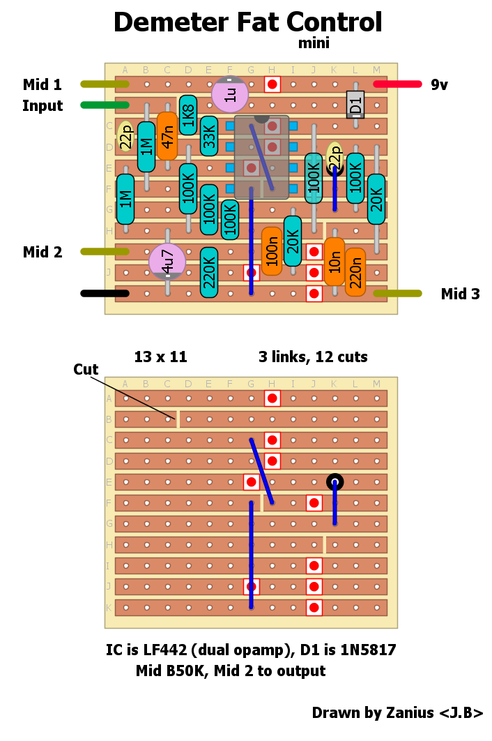
I found this information about 10n and the 100n caps replaced by 220n cap, I'm not sure about that mod, and I really like to get the Tyler mid boost real schematic.
If you change the 10nF with a 220nF I think you will get an extremely muffled sound. You can try it, and hear what sounds you really get.
While, change the 100nF with a 220nF should add low end.
Now some speculation.
I found some images of the original PCB with just one electrolytic cap (the one in the PSU, I suppose), three 220k cap (220nF) one more then stock Fat Control pedal, and two greenie caps.
We can assume those are the 47nF input cap and the cap across the VB (10nF in the stock pedal).
This could mean the 1uF electrolytic cap is one of the cap replaced by the 220nF. This has effect just when the boost pot is lower, and it gives more low end (if there's no other mods!). I can't understand totally this thing.
I'm not sure about the value of the two greenie cap.
The input cap could be 47nF: there's no difference if you change it with 22nF or 100nF. I'm not sure about the other greenie cap, it seems a bit bigger than a 10nF.
A thing that me confused is another version of the PCB with a fat red box wima style cap, I'm not sure that could be a small value like the 10nF cap or just a bit more than it.
Here's you can find some circuit image:
https://reverb.com/it/item/13109056-james-tyler-mid-boost-circuithttps://reverb.com/item/28173931-james-tyler-demeter-midboost-and-buffer-combo-pedal-redAnd here's there a picture of a schematic drawn, but not so clear, unfortunately.
Page:
https://studiogream.blog.fc2.com/blog-entry-126.htmlSchematic:
https://blog-imgs-55.fc2.com/s/t/u/studiogream/DSC08835.jpgThere is where I see the 1uF replace from a 224 bipolar cap. And even the resistor before that cap: 2.2k instead 1.8k.
The 100nF in VB seems to be, indeed, 220nF.
I can't tell if the 10nF cap is a 10nF.
That's it.
I build pedals