Diefet problem - low volume and gain, sounds thin
12345


12345
|
Hi guys,
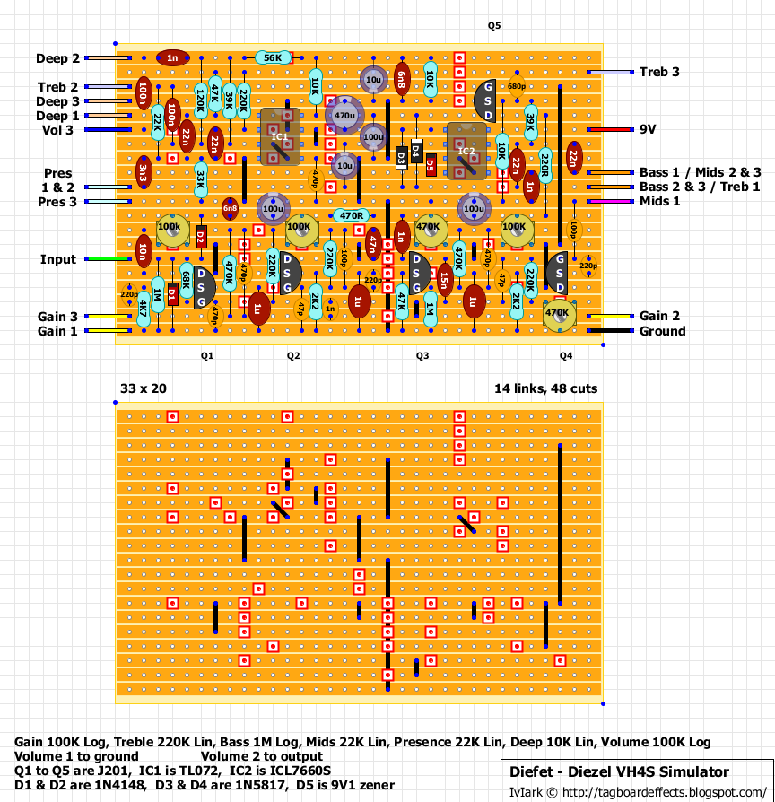
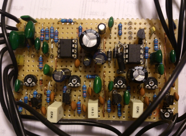
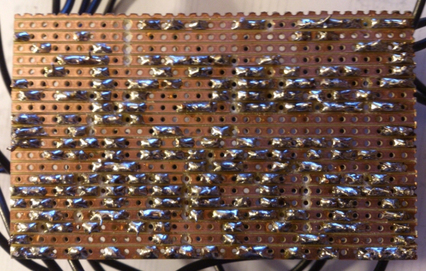
I just built my first pedal the diefet, and I have tried for the last four days to find the solution to my problem but I think I am loosing it now, so if you could help in any way I would be very gratefull. Problem: 1. very low volume, if I max the volume the signal is still lower then when I bypass the pedal. So when bypassed the signal is normal 2. very low gain, I have to keep it max to have some gain, and it sounds thin. 3. high pitched background buzz even when using battery, found out that when I remove icl 7660s it stops. But the first two problems remain. I used the vero layout  my vero board:   already tried: 1. checked the layout if it is correct 2. checked that there are no connections between cuts 3. used scalpel to possibly remove connections between copper lines 4. remelted the solder on all conecctions including pots and wires so that to remove possibility of cold joint. Info: 1. when bypassed signal is normal like it has to be, input voltage is 9V 2. all pots function i.e. increase and decrease the value 3. chips are TL072CP and 7660s CPAZ 4. all values are the same as layout exept one cap is listed as 100uf 25V but mine is 100uf 35V 5. jfets: Q1: 8.3 Q2: 9.25 (cannot get lower) Q3: 8.66 Q4: 9.4 q5: 16.36 6. TL072: pin 1. 8.3 2. 8.3 3. 7.54 4. 0.0 5. 7.55 6. 8.32 7. 8.2 8. 16.38 7. 7660s 1. 8.56 2. 4.83 3. 0.0 4. 0.0 5. 0.0 6. 3.02 7. 5.56 8. 8.56 Please, any suggestion is more than helpfull, thanks. |
Re: Diefet problem - low volume and gain, sounds thin
|
Have you tried an audio probe to find where the problems start?
Also are you 100% certain that your j201 transistors are legit? I had so many headaches buying j201's that were out of spec and my circuits never worked properly. Changed to smd ones with adapter boards a few years ago and haven't looked back since. |
|
I would focus on Q2. If you tried to bias that JFET and you couldn't get the drain voltage lower than 9V, the JFET may be bad. Put another one in there (even a non-J201 like a 2N5457) and see if you can bias it.
|
|
I bought from banzai music shop.
I tried changing q2 with another j201 and still cannot get lower than 9 v. I made diy audioprobe, and dont know what to look for particulary. I tried audio probe on all drains and it very loud (compared to ouput point) and last two jfets are distorted but not bone crushing distortion more of a crunch. (gain and volume pots maxed). Even if I lower voltage on the last jfet trim it is still not high gain saturated sound. When signal enters tone stack it gets lower all over the place because of all the resistors.. Tried probe on pots, bass mid treble are probably 3 times louder than output point, deep, presence and volume pot similar to output point. gain pot is very low volume (lower than ouput point) and clean sound (when it is on max). |
Re: Diefet problem - low volume and gain, sounds thin
|
Like Frank said, Q2 seems suspect since you can't bias it to 1/2 the supply voltage.
|
|
Check your board for any solder bridges, especially in the vicinity of Q1 and Q2 (lower left part of the board). You should be getting a lot of gain through Q1 so if the Gain pot is low volume compared with the Q1's drain, there must be something going on in that area. By the time you get to Q3, Q4, the gain should be quite big.
Do you have any other JFET's (say 2N5457s)? If so, try those in Q1 and Q2, and rebias. The gain will be lower but it still should work. |
|
ok,
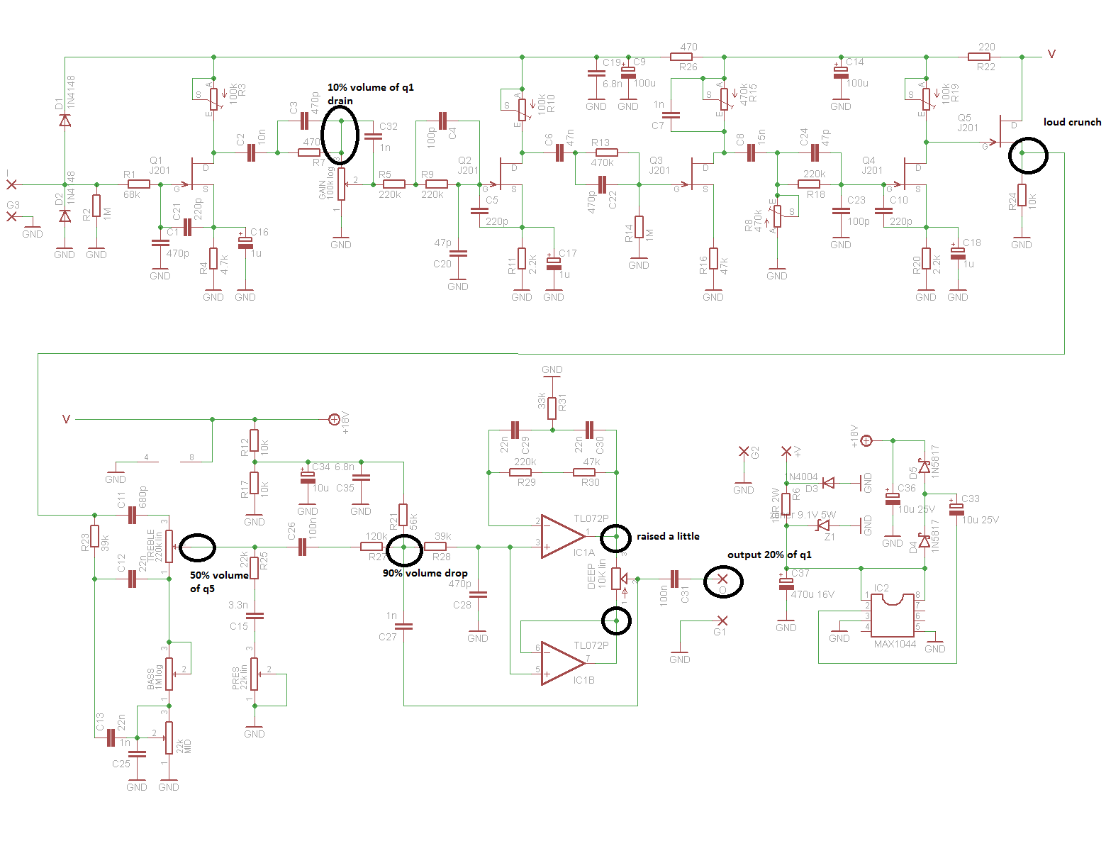
i replaced q2 and q5 and now i can go lower voltage on q2. guess the first time replaced with the same jfet. yes drain on q1 is very loud compared to gain pot. I traced with audio probe and the signal gets very quiet after it passes 470p and 470k before reaching gain pot, then it further drops before it reaches gate of q2. I fell that the drain of q1 and q2 are the same level of gain, cannot perceive any difference. Should i measure anything else regarding jfets? |
Re: Diefet problem - low volume and gain, sounds thin
|
my experience in the past with those jfets were that even if they seemed to bias properly, they still didn't sound good.
|
|
In reply to this post by marcus262
Double check the 47p from Q2 gate to ground. Are you certain it's 47p? |
|
yes I checked.
just to summarize (volume and gain pot maxed): 1. gain pot lower volume than q1 drain (massive difference) - like 10% of q1 2. at q5 loud volume but only crunch not (high gain) - volume like q1 drain 3. at treble pot lug2 volume decreases 50 % compared to q5 4. after 120k huge volume drop 90% 5. tl072 raises it by little and that is output volume so it is lower than q1  |
|
Thanks Marcus for your thorough testing of the vero.
I decided to research this at DIYStompboxes - there's a big thread over there on this circuit: http://www.diystompboxes.com/smfforum/index.php?topic=70800.0 My thoughts... (1) The volume drop at the Gain pot doesn't surprise me now after looking at the schematic. Since the Gain pot is only 100K (compared to 1M for the similar Dr. Boogey), the voltage divider formed from the 470K and the 100K pot means a lot of the signal is dumped. That may be intentional so as to not have a high amplitude signal being clipped massively by the subsequent stages. Nevertheless, you can try substituting a 1M pot for the Gain and see if that helps the volume. (2) Others have complained about the low output. Again, I'd try a 1M Gain pot. (3) Did you try biasing each JFET individually by ear? That is, start with Q1, adjust the trimmer until the output is loudest and clearest, then move to Q2, Q3, Q4. I wouldn't worry too much about the drain voltages, and just trim by ear. (4) If you want to wade through the original French thread at Techniguitare, here it is: http://techniguitare.com/forum/realisation-montage/diefet-simulation-ampli-diezel-vh4-t7386.html I've built the Dr. Boogey (great circuit!) and this is quite similar except for the tone stack and other filtering at the end. The main difference I see is in the Gain pot value. You could also try playing around with other resistors in the audio path, but I think the only way to recover more volume would be to tack on a recovery stage at the end (perhaps a single op amp booster). Or you could perhaps mod the existing op amp circuit to provide both a boost and filtering. Anyhow, let us know if you find anything that works. |
|
thank you for trying to help.
1. replaced the gain pot for 1m, volume increased a hair, nothing noticable. 2. those who coplained about volume had a cap and resistor before output, but this schematic omits them, so I should be getting full volume. 3. tried by ear, still in crunch mode. Thanks again everyone for all your help, but I just cannot seem to find a problem, i might as well drop it altogether. Maybe Peter Diezel did some witchcraft recently that "you shall not copy a diezel amp" :) |
|
Tried to recreate the level of gain and volume using crappy behringer ultra metal pedal.
So, if I have volume and gain on 100% on diefet it matches 10:30 o'clock volume and 8 o'clock gain (barely turned up, cause 7 o'clock is zero on behringer) |
Re: Diefet problem - low volume and gain, sounds thin
|
I've built quite a few of these pedals. gain at noon on the diefet is usually more than enough. when you adjust the trimmer for Q2 does it bias at all, or is the voltage constant?On Tue, Mar 22, 2016 at 8:28 AM, marcus262 [via Guitar FX Layouts] <[hidden email]> wrote: Tried to recreate the level of gain and volume using crappy behringer ultra metal pedal. |
Re: Diefet problem - low volume and gain, sounds thin
|
I have also built a couple of these. It is a very complex circuit but it is loud. I would just keep looking for bad cuts or misplaced parts.
Audio probes often lead you to a problem area - but the point where volume drops off is not always the exact component you need to fix. Often it is a bad cap in the area, or a resistor of the wrong value. ALSO, I have found the trim pots can be problematic. They can short out. Be careful when turning them, use plastic screwdrivers if they have exposed metal, replace if you are not certain about them. |
|
all jfet can bias, voltage varies as I turn.
When using probe, q1 is clean, q2 still clean to my ears, q3 start to break up, q4 and 5 are distorted heavily compared to q3. If one jfet was bad, I would get no signal on audio probe, right? Is tl072 supposed to amplify anything cause I hear very little difference between output and input of the chip. I checked for cuts and parts, parts are in correct position and i ordered correctly. Cannot check if the caps are functional, my meter doesnt do that. Also, went with scalpel again between lines, reheated and applied more solder on every joint. |
Re: Diefet problem - low volume and gain, sounds thin
|
You should hear breakup after q1 for sure.
On Tuesday, March 22, 2016, marcus262 [via Guitar FX Layouts] <[hidden email]> wrote: all jfet can bias, voltage varies as I turn. -- Sent from Gmail Mobile |
|
Can you measure the drain, gate, and source voltages for Q1 - Q5? Thanks.
|
|
This post was updated on .
yes, sure.
btw, the more I turn clockwise I just loose gain and volume, so it sounds best ccw. but when biased half suply voltage, here it is: q1 - D 8.38 S 0.53 G 0 q2 D 8.70 S 0.23 G 0 q3 D 8.57 S 0.67 G 0 q4 D 8.82 S 0.28 G 0 q5 D 17.43 S 8.11 G 8.86 so, q1 drain is clean and louder compared to input, q2 is clean same volume as q1, q3 begins to distort but same volume as q2, q4 and q5 are both very distorted and louder compared to q3. Breakup only begins on q3 Sensei Tim |
|
Hmmm. The bias voltages look OK to me. The only thing I can think of is that something is wrong with the 1uF source bypass capacitor on Q2. The bypass caps on the JFETs increase the gain quite a lot, so if the connection was bad, it would reduce the gain enough to explain the "clean crunch" sound you're hearing.
Check all the JFET connections with your continuity checker. Check all of your cuts too to make sure there isn't a hidden bridge. |
«
Return to Open Chat
|
1 view|%1 views
| Free forum by Nabble | Edit this page |

