Diodes on a switch

classic Classic list List threaded Threaded
7 messages Options
Reply | Threaded
Open this post in threaded view
|

Diodes on a switch

vid.sicious
Hey there guys! Hope you're having a wonderful day. I've been haunted by this idea of a very modded Proco Rat for a while now and luckily I found the Mightier Mouse illustrated mods on Beavis Audio but it still is slightly unclear to me as these are based on BYOC Rat clone and not vero. I've been wanting to add a diode selector switch on my next rat and at first I thought that this illustrates it but from a second look, it seems like it's an Overdrive mod which clips the signal after or before the diodes. Anyhow, this Overdrive mod seems awesome and the MOSFETs are already on the way. I've got a question about the diagram below though. I'm planning on making the Compact Proco Rat layout but I'm very unsure as to where I should put the wires for the OD mod. Could someone point the holes out for me? And from what I understand, you still keep the stock diodes on the board, right?


Now, another question, I'm pretty new to this as I've not experimented with diode switching yet but what if I wanted to also include a diode selector switch along with the overdrive mod? Let's say: No diodes; stock diodes; red LEDs. How would that interact with the OD mod? Is it even a good idea? If you have any good diagram or advice on what's the best way to include a diode selector switch regardless of the OD mod, that'd be greatly appreciated! My first Rat build sounds so insanely good, I want to make one with all the mods possible.

Thanks for all the help and support.
aka Dead Eye
Reply | Threaded
Open this post in threaded view
|

Re: Diodes on a switch

induction
Both of your requested mods are fairly easy to work into the layout.

OD mod: Without a schematic I can't be absolutely certain, but the blurry article indicates that the diodes will go in the feedback loop of the op-amp. Luckily, the gain pot is also in the feedback loop of the op-amp, so you can put one of the red wires in the OD mod diagram on Gain 1 and the other on Gain 2 & 3. Make sure your DPDT is on/off/on.

Diode switch mod: This mod is exactly the same subcircuit as the OD mod, it just goes in a different place in the circuit. So copy the DPDT on/off/on switch from the OD mod: anti-parallel leds on one side, anti-parallel stock diodes on the other (or whatever other combination you come up with). Remove D1 and D2 from the layout. Leave D1 empty and replace D2 with the red wires from your new clipping switch.

Nobody knows if you'll like the mods or not. You'll have to use your ears for that. If you want to know whether you like the mods enough to use up your component stash on them, you could breadboard it first. It's the only way to know for sure.

Reply | Threaded
Open this post in threaded view
|

Re: Diodes on a switch

Ciaran Haslett
In reply to this post by vid.sicious
Induction is spot on.  When you start talking about modding circuits as opposed to just cloning layouts, I think its important to begin learning how a circuit works.  Take your requested clipping options for example.

If you look at the Rat schematic here you can see the output voltage is fed back to the opamp input (the amount of which is controlled by the Distortion pot).  This is where a Rat get s most of its clipping...from the opamp.

If you compare that with the Tube Screamer here you can see the exact same thing.  Only now the tube screamer has a pair of back to back diodes thrown in.  These diodes clip the voltage output of the opamp being fed back to its input symmetrically (waveform clipped equally on its positive and negative swings)

MOSFETs have diodes inside them to protect them from static shocks...but they are diodes like any others so can be used just like the 1N914s in the tube screamer.  So... the OD mod you specified is just some MOSFETs (being used as clippers) injected into the Rats feedback loop.  But now we know a little bit more of whats actually happening so we can experiment a bit.  For example....if you use an on/off/on for the OD mod, you can have a choice or 2 different options on each end of the switch or stock in the middle.  Follow inductions instructions for that.  

Now for the 2 diodes to ground.  These are whats known as a hard clipping pair.  When the voltage potential of the opamp to ground is larger than the forward voltage of the diodes they turn on and clip any signal beyond their forward voltage. The back to back pair again makes sure the clipping is symmetrical.  So what happens if you remove the diodes?  There's no forward voltage threshold so no hard clipping occurs so we get some more output.  Or change them to LEDs?  Well...LEDs have a typically higher VF than small signal diodes therefore a higher threshold before clipping (in this hard clipping setup) that would probably make for a more subtle clipping option in this case.  Or try germanium?  Or even a series pair paralleled with on opposite? (This creates a different forward voltage in one direction to the other creating asymmetrical clipping)

With the hard clipping diodes you could do the same as or feedback loop example.  Stock arrangement on one side, your personal arrangement on the other side and leave the middle off to act as a diode lift.  And once more...what will actually sound good is entirely up to you.

Again, knowing just a bit about how a circuit works can really open up our possibilities for modding.

I can happily say that the more pedals you build, the more you will start understanding how it all actually works.  Also read this and this....oh....and this.  Between all this links you will pretty much be able to dissect ANY dirt pedal you will ever build into its constituent parts for prime Vid Sicious Booteek Uber Magik Wunder Pedals and sell a YATS for £1000
Reply | Threaded
Open this post in threaded view
|

Re: Diodes on a switch

vid.sicious
Thanks so much for all the help guys! Induction, I will follow your advice and see if I like any of the mods. I'm just building it for the heck of it. Need to learn more about modding and what's a better way to do it than making the mods myself. Ciaran, your detailed post is greatly appreciated and the links are great too! I just built my first Big Muff and Fuzzface so these analysis will be great for getting to know better how them 2 pedals work. Need to get my hands on a Tube Scremer too. I will build the modded rat and will post details about results. I have reuploaded the schematic on Rat mods in higher definition which you can find HERE. Thanks a lot!
aka Dead Eye
Reply | Threaded
Open this post in threaded view
|

Re: Diodes on a switch

Silver Blues
If you want to know everything about Muffs, you need to check out Kit Rae's site. Required reading for anyone into Muffs.
Through all the worry and pain we move on
Reply | Threaded
Open this post in threaded view
|

Re: Diodes on a switch

vid.sicious
Nice. The person who made the Muff website must have an obsession  
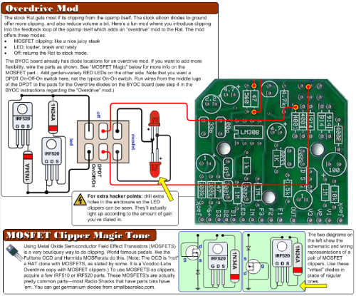
I am a bit unsure of the illustration above slightly again. What is the purpose for the diodes paired with the MOSFETs? Are they a necessity?
aka Dead Eye
Reply | Threaded
Open this post in threaded view
|

Re: Diodes on a switch

Ciaran Haslett
Not a necessity no.  A lot of dirt pedals tend to have 4 diodes in the feedback loop.  If you wanted you could add more.  It all just changes the flavour of clipping.