Dual board wiring, but only one active at a time

classic Classic list List threaded Threaded
11 messages Options
Reply | Threaded
Open this post in threaded view
|

Dual board wiring, but only one active at a time

jaredcohen
I posted this on the Madbean Cave Dweller but I realize this is a better place since it's not really pedal-specific.

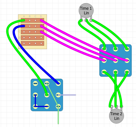
I used to have a BBE Two Timer and really liked the switching concept. Footswitch 1 selected between two different delays, and footswitch 2 turned the pedal on and off. I think the advantage over typical dual-effect wiring, for me, is that only 1 of the delays can be engaged at a time, and if I accidentally enable a second delay even for a second, it's going to linger. Footswitch one had 2 LEDs (to indicate which board was active, so one of them was always lit), and footswitch 2 just had a typical on/off LED.

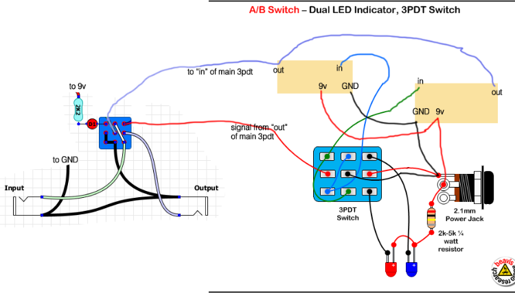
I'd like to put 2 Cave Dwellers in one box.  I looked at the Beavis site a lot today and tried to modify his A/B w/ LED to fit what I want... just wondering if anyone will take a look and see what they think.  I sincerely apologize for this drawing - not an Illustrator wiz.

Thanks all.  

Reply | Threaded
Open this post in threaded view
|

Re: Dual board wiring, but only one active at a time

Lazy Swamis
Looks like it should work to me. The only thing I see that may be a problem (or might be really cool) is that the delay board "outs" are always live until the effect(s) are bypassed at the main switch. So on long settings there will be some overlap in the signal when you switch from one to the other. A 4pdt could solve that.
Reply | Threaded
Open this post in threaded view
|

Re: Dual board wiring, but only one active at a time

jaredcohen
Lazy,

Thanks for the reply. Good catch about the out always being live. You're right it might end up cool, but it might also really get in the way...

As for a 4PDT, would that be as simple as sending the out of Board1 to the top of pole 4, the out of Board2 to the bottom of pole 4, and then use the middle lug of pole 4 to go back to "signal in" of the main 3PDT?

Thanks.
Reply | Threaded
Open this post in threaded view
|

Re: Dual board wiring, but only one active at a time

dexxyy
In reply to this post by jaredcohen
The BBE two timer doesn`t have 2 delays, its only a single delay with 2 time pots wired up to a switch. To get the same effect with any delay you just need to wire the three time wires to the middle of all 3 poles on a 3pdt switch then wire 1 time pot to the upper 3 lugs and the other to time pot to the 3 lower lugs. There is no bleed over of delays as you are basically switching in a different resistance ie between 2 pots set at different levels.
If it wasn't for this website I would definitely have a life.
Reply | Threaded
Open this post in threaded view
|

Re: Dual board wiring, but only one active at a time

jaredcohen
Dexxyy,

You just blew my mind.  That's a hell of a lot easier than I was thinking.  I still might use the 2 boards, with one as a Cave Dweller and one as a Cave Dweller II for way longer delays.  Or if I just wanted two completely different delays in the box to choose from.

So are you just suggesting something like this image?  Sorry, but I'm a visual person, and if I don't see it drawn out I'll never understand it. I waste a lot of time just drawing things to get them through my thick head.

I really would like indicator LEDs to tell me which delay time is engaged... I can't just stick an LEDs into the respective lugs, can I?

Reply | Threaded
Open this post in threaded view
|

Re: Dual board wiring, but only one active at a time

IvIark
Administrator
It wouldn't involved the stomp switching at all.  The Time 1 wire would go to the centre contact of one pole, the Time 2 and 3 wire would go to the centre contact on the second pole.  Then the top two contacts would connect to Time 1 and Time 2 & 3 of Time pot A, the bottom two contacts would connect to Time pot B.  So then one pot would be in circuit, as you stomped that would be disconnected and the second pot would be put in circuit.  Then whatever time levels you had pre-set at the respective pots would automatically be applied to the PT2399.

That's one of the things I love about this IC, it's really easy to get it to do some pretty funky stuff.
Reply | Threaded
Open this post in threaded view
|

Re: Dual board wiring, but only one active at a time

dexxyy
In reply to this post by jaredcohen
Yeah that`s it, just remember that the wires from the board need to correspond with the pot numbers, ie time 1 from the board to the middle lug has to connect to pot lug 1 on the upper and lower lugs etc. Unfortunately for led indication you will need a 4th pole therefore a 4pdt switch would be required.
If it wasn't for this website I would definitely have a life.
Reply | Threaded
Open this post in threaded view
|

Re: Dual board wiring, but only one active at a time

jaredcohen
Thanks Mark and Dexxyy,

It never ceases to amaze me how much you all know. Thanks for putting up with my questions.

Dexxy, on a 4PDT would that just be anode of LED1 to the top lug of pole 4, anode of LED2 to the bottom lug of pole 4, and grounds to the center lug of pole 4 (with resistors in place, of course)?
Reply | Threaded
Open this post in threaded view
|

Re: Dual board wiring, but only one active at a time

dexxyy
Yeah, but as Mark has noted, as time 2&3 are connected you only need 2 poles for the pots so a 3pdt will do as the 3rd pole can be used for the leds. Personally I would use a dual colour led with common cathode (cathode connects to ground)  just to make it tidier and 1 less led hole to drill
If it wasn't for this website I would definitely have a life.
Reply | Threaded
Open this post in threaded view
|

Re: Dual board wiring, but only one active at a time

jaredcohen
Thanks again guys. Time to get drilling and soldering. Let's see if I can make it happen.
Reply | Threaded
Open this post in threaded view
|

Re: Dual board wiring, but only one active at a time

Neil mcNasty
Since Lug-1 of the Time pot is a ground connection, you could also use a DPDT stomp and attach the led (ground connection) to the same pole as the one going to the  Lug-1 of the Time pots.
I've done this for several of my builds and it has not given me any trouble or switching noise.

Sometime I've also jammed in quite a lot of functions on a switch, using only the ground connections from the pots wired to the switch and soldering the other leads directly to the board (you'll need two holes on the vero to connect at the same spot), so that I then could be able to switch between two different settings involving 4 pots connected to a 4PDT switch.