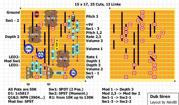
Dub Siren.
123
123
|
Sorry to crash the project! I built the V3 layout of this circuit today and tested it on the breadboard. It's making the right noise and all the pots and switches seem to be working properly. But the LEDs aren't working and the opamp (ne5532) gets hot after running it for a few minutes. It does sound pretty cool though!
|
|
There was a mistake: you need to remove the link between NE555 pin 4 and the transistors' emitter.
The emitters need to be connected to ground. I must be getting old!  
|
|
In reply to this post by D$
Hey DS, no need to apologise - that's exactly how this forum is supposed to work. Someone puts up a request (me), someone is generous enough to reply with a layout (Alex), then we all collaborate to make sure it works. Everyone ends up happy!
The way I have the Mk.II version working now is as follows: The led connected to Switch #1 (the permanent on/momentary on switch) should light up in one position (permanent on) and go out in the other position (the momentary) position. It should then light up every time you press the momentary switch. The other LED connected to the Mod switch, should flash on and off with the rate and depth controls, or be permanently on in the other switch position. Try connecting a wire from the centre lug (2) of the Mod switch, and the base pin of Q1 (left hand side of the board, second row from bottom). This is what I did on the Mk.II version to get the LEDs working correctly. If this gets the LEDs sorted, let us know and Alex can amend the layout. |
|
Hi Mark
The 68K on version 2 was going to the wrong NE555. V3 (latest version) now matches the schematic but let me know if your version came out better. |
|
Hey Guys! I removed the small link from 555 pin 4 to transistor emitters. And made a new link from emitters to ground and the LEDs fired right up. I believe everything is working as it should now. One LED flashes with the rate. And the other "momentary armed" LED only comes on when the switch is in the momentary trigger position. Im probably going to box it up with a cave dweller delay to get a more spaced out drone box.
|
|
This post was updated on .
In reply to this post by Alex
It sounds like my mods to version 2 (move top connection of left hand 68k up a row to transistor base, and wire between Mod switch lug 2 (centre lug) to row 2, left hand side of the board) and Da$t's description of the way his LEDs are working are not quite doing the same thing.
With my "mods", I'm getting the same as Da$t from the Mod switch, but the permanent/momentary switch works differently (and more logically). I'm getting the LED lighting up when in the "permanent" position, then going out when switched to "momentary" position. It will then light up every time I press the momentary button. So I think the way mine works is "better"??? Seems more logical at least. I tried wiring the 68k resistor to pin 3 on the other 555 as you suggested, and got the Mod LED pemanently on, but the perm/mom switch acting like Da$t describes. So a biy of a failure there. I would be tempted to reinstate version 2 with my "corrections" and call it verified. On the plus side, I've found a cool hack for this circuit. If you take a wire from the unused lug 3 of the mod switch and connect it to ground via another switch or push-button (either permanent or momentary), you can get a whole extra range of drones bleeps and whistles! |
|
This post was updated on .
I built v2 layout (incorporating Mark's suggestions). Cool noise box.
 All is functioning, except that the rate LED does not flash in time when the mod is engaged. Also, the sw2 LED indicator lights up when switch is momentarily engaged, but only in the sw1 ON position... Which is backwards to how it should function, I'm guessing? As others have mentioned, there is bleed through when sw1 is in the off position. This thing is pretty sweet as is, but it would be awesome if I could iron out those three kinks. I'll let you guys know if I figure it out. If by chance any of you guys have already figured out a fix, I would be grateful if you could share that info. Thanks so much to Alex and Mark for the layout and suggestions! |
|
In reply to this post by Alex
Hi! It's my first time here and I find this very interesting! Is this layout working properly?? Thanks for your help!
|
|
In reply to this post by Beaker
If you are having signal bleed issues try upping the 2k2 between pin 6 and the pitch pot to 4k7.
|
|
I built this and even after upping the 2k2 to 4k7 and then to 10k, I'm stll getting signal bleed when the switch is unengaged.
I'm wondering if we can get a fully updated layout with the adjustments for the status LED to function properly. I tried to wire it up as described, but it didn't change the way the LED operated, so I must have misunderstood. Thanks to everyone who has worked through this! |
|
Quick update:
I switched out the on-on spdt (sw-1) for an on-off-on spdt and when it's in the off position the signal bleed is almost entirely gone. It's not an ideal fix, but it makes the thing workable at least! |
«
Return to Synths & Noisemakers
|
1 view|%1 views
| Free forum by Nabble | Edit this page |

