Earthquaker Devices - Tone Reaper
|
Hello,
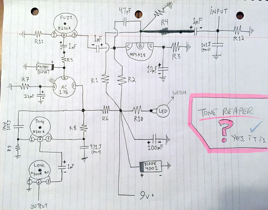
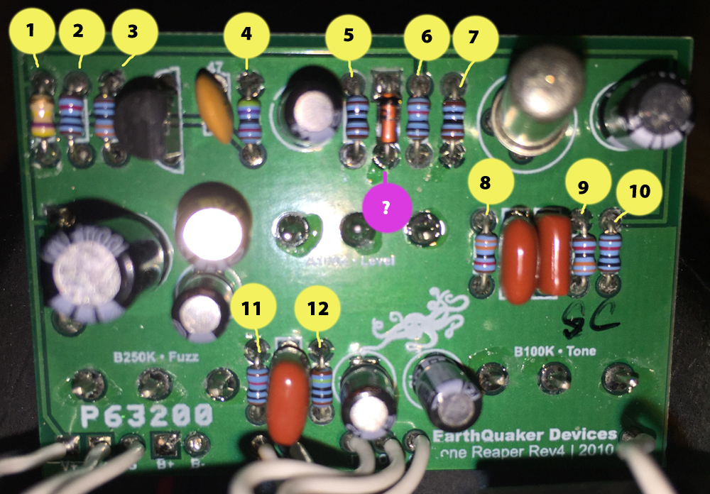
Here is a request/offering for the site. As a new hobbyist, I wanted to contribute something to the community, so I took a stab at tracing my Tone Reaper. As you can tell from the pics, I obviously don’t know the proper way to go about drawing a schematic. However, it DID work on a breadboard with substitute NPN Si transistors and a couple incorrect resistor values. So it's a good launch point, I think. I hope you'll get the jist of it even without all the proper symbols/notation. That said – I need some help identifying values. The resistors are mostly tiny 5-band metal film ones, and I can’t be sure that I’m interpreting them correctly with my inexperienced eye (might be backwards?). So there’s also a photo of the guts, and I wrote down the actual color bands. Lastly, there’s a diode marked “mystery” because the code isn’t visible in its current position on the board, and I’d rather not desolder it with my beginner skills. If anyone else has a Tone Reaper and can see the code on theirs, please share! Thanks for this amazing site! -Dan Resistors 1-12 R1: 470K - carbon film, 4 band: Y, V, Y, Gld R2: 10K? – Brwn, Blk, Blk, Rd, Brwn R3: 330R? – Or, Or, Blk, Blk, Brwn R4: 47K – Y, V, Blk, Rd, Brwn R5: 1k? Brwn, Brwn, Blk, Blk, Brwn R6: 10K? – Brwn, Blk, Blk, Rd, Brwn R7: 1k? Brwn, Brwn, Blk, Blk, Brwn R8: 33k? Or, Or, Blk, Rd, Brwn R9: 33k? Or, Or, Blk, Rd, Brwn R10: 10K? – Brwn, Blk, Blk, Rd, Brwn R11: 10K? – Brwn, Blk, Blk, Rd, Brwn R12: 1M? – Brwn, Blk, Blk, Y, Brwn   |
|
Administrator
|
Interesting so it's a MKIII tonebender with the Darlington pair replaced with a single high gain Si transistor
|
|
Administrator
|
interesting, not what i thought it was. i'll take care of it tomorrow and post it on the main page after my exam.
|
|
Administrator
|
great job on the trace, figuring the values, and posting what it is.
 resistors look good to me, and i've uploaded the layout to the main page. the one thing that i'm not sure of is the 101 and 471 caps, which would be 100pF and 470pF respectively being poly. i think they may be silver mica caps, since i haven't seen poly caps below 1nF. given that MLCC or plane old ceramics would be fine. also, just one note, nothing wrong or bad, but the schematic is all over the place so it's not the easiest thing to follow. when you make them, especially when tracing it helps to try and keep it organized and have it flow from input to output, and have a single row for power. it not only makes it easier when trying to make a layout, but it also helps you when tracing to make sure you've got it all right, and what even more important is that you can better understand whats happening. |
|
Awesome! You're quick. Thanks for giving everything an experienced look-over.
I barely know how to read a schematic at this point, so I just took my best shot at imitating one when tracing, and that's how it came out. (Luckily it worked when testing.) Do you happen to know if there's any sort of guide to tracing circuits or schematic writing for the average joe? While this was the only pedal I own that wasn't already on this site, I'd be happy to try more traces in the future if I get some worthy pedals, and also learn the right way to go about it. Any links would be appreciated. Thanks again! -Dan |
|
Administrator
|
honestly i'm sure there are some out there, but i don't know of them. there may be some stuff posted in the library. what i did was i used existing schematics and tried to follow it along when looking at the trace of the PCB on a pedal. tbh, i kinda jumped right in by looking at the big muff, since there are so may schematics and explanation of what's going on at each part of the circuit. just google some circuit schematic, and you'll see how they're laid out. if i can help anymore just ask and i'll try my best to help.
it's hard to trace an effect without having either good pictures top and bottom, and sometimes parts have to be removed to see where certain traces go. |
|
In reply to this post by Galapagos
Get a Tonebender MKIII schematic and see what matches up. You'll pick things up quickly after that.
|
Re: Earthquaker Devices - Tone Reaper
|
In reply to this post by Galapagos
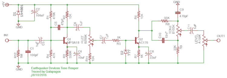
Redrew the schematic. C9 and C10 are the caps under question.

|
|
Administrator
|
Thanks Ciaran. I'm copying my post from the main page..
Are we sure about the tone stack? The tone stack in the MKIII is not like the one in the BMP. The MKIII tone stack basically pans between a tiny output cap and a big output cap. If this were the case, the 4n7 is certainly the correct choice vs the 470pf I'm wondering now if the tone stack was traced correctly, or if EQD simply used a BMP tone stack instead.. Take a look at a MKIII schematic and let me know what you think guys. As I see it this is an error or a less effective BMP tone stack |
Re: Earthquaker Devices - Tone Reaper
|
Good point Travis.
Galapagos...is it possible you mixed up the positioning of R8 and the 471 cap? The tone bender has the cap going to V+ instead of ground and R8 going from that junction to GND. Worth noting the Colorsound Jumbo Bender has a BMP stuck on the end with 10n and 3n caps and 33K resistors. Either way, the BMP and the TB tone controls are the 2 most likely candidates. Would you mind having another look? Cheers |
|
Absolutely. Here are some pics to help answer that as best I can. They are:
1) Two legible shots of the printed capacitor values 2) Side by side from the soldering side of the PCB, with my tracing drawn over the top as I interpreted it 3) Side by side from the mounting side of the PCB, with tracing over the top again Lastly, my interpretation of the tone sweep on the real pedal is that it isn't especially pronounced. Some of the youtube videos that are less produced make that easier to hear. So despite these values being strange, I'm not sure that they're "wrong." When I was swapping in 4.7nf for instance (in for 470pf), the sweep was then quite a bit more pronounced than the real pedal. But that's strictly my ears telling me that, so take it with a grain of salt. If I can help with anything else, just tell me what you need and I'll do my best. -Dan   
|
Re: Earthquaker Devices - Tone Reaper
|
Yip...that settles it. You were spot on! BMP tone control with less than ideal cap values (compared to tradition). Excellent job on the trace Dan.
Only thing puzzling me is why the 470pF cap is much bigger (physically) than the 10nF. My experience has always been, the bigger the value, the bigger the size. Don'y suppose you have a meter that measures capacitance? You could test both caps without removing them. The results won't be vary accurate but should be close enough to guess. But aye...other than that, really great job lad. Cheers |
|
Administrator
|
Could be larger due to a higher voltage rating. EDIT: nope looks like both are 100v.. Well well!
I do have 470p film caps but never seen 100p! |
|
Administrator
|
I've seen boards with that cap being mlcc and some with it being silver mica. This board still confuses me we to the value of some caps because they all appear to be Mylar and I've never seen a Mylar in pF like that.
|
|
Unfortunately I only have a cheap multimeter, no capacitance meter. I'm too new to this hobby to justify buying new equipment, but I'll have a look at some of the gear pages of the forum and consider picking up a cheap one to solve this mystery.
|
|
This post was updated on .
Galapagos, does your original get bassier as you turn the tone knob to the right?
|
|
Yes it does. Seems "backwards" from a typical tone control, but that's what it's doing.
|
«
Return to Requests
|
1 view|%1 views
| Free forum by Nabble | Edit this page |

