Escobedo,BRONX CHEER

classic Classic list List threaded Threaded
4 messages Options
Reply | Threaded
Open this post in threaded view
|

Escobedo,BRONX CHEER

Synsound
This post was updated on .
I have ordered a few PCBs from General Guitar Gadgets and thought I would try my hand at a vero layout on this one while I waited for it to arrive. This is my first attempt at making a layout and I have prob messed up somewhere. I used this schematic from teir page. If someone could give it a once over, I would greatly appreciate it.

Give a man a match and he'll be warm for a day.
Set a man on fire and he'll be warm for the rest of his life.
Reply | Threaded
Open this post in threaded view
|

Re: Escobedo,BRONX CHEER

rocket88
Administrator
not bad for a first vero man. few things i've caught.

1 - the transformer should be connected to the 1M at the input, not ground.

2 - the 47nF should be connected to the other leg of the transformer, and connect to the diodes.

3 - it looks to me like there ground is not connected to the bottom row.

4 - im not sure about the transformer legs. should there be 2 connections or more?

once you fix those you should be able to line up the rest correctly.

something that i think about when making layouts that helps me is that i think about everything as a map for a town, and the circuit is the streets. when you place components you'll see where multiple components connect, that's like your intersections, and when you look at your vero you should see the exact number of connections at the same relative positions. so if you look at the 47nF cap you should have one side connecting to one leg of the transformer, and on the other side you should have 3 connections, - leg of D1, Base of Q1, and + leg of D2. you see what i mean?

i also usually start at the input and work across to the output, and fill in the rest afterwards, it's actually the same way i approach breadboarding.
Reply | Threaded
Open this post in threaded view
|

Re: Escobedo,BRONX CHEER

tabbycat
In reply to this post by Synsound
hey synsound, just wanted to say congrats on translating your first vero layout.

i did my first in january so know what a kick (and a struggle) the process can be. an unexpected knock on of doing my frist one was that i was suddenly able to read other people's layouts so much quicker than i had been able to before, just for having concentrated enough on one of my own. that was a sweet pay off.

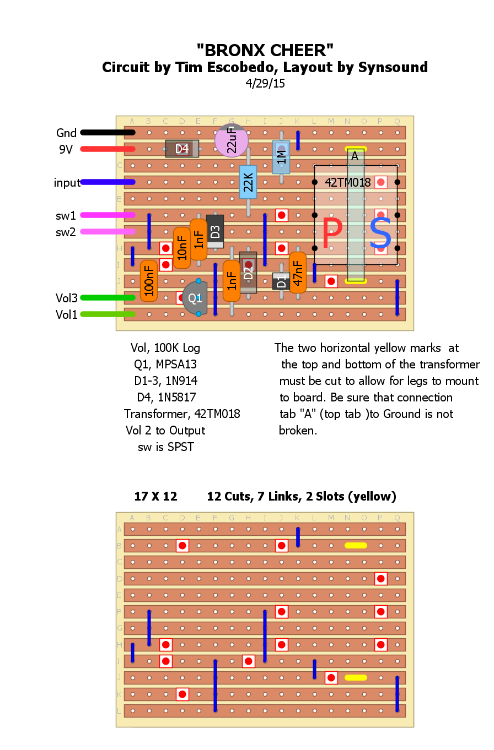
re your layout, just had a very quick look and rocket88 knows this better than me and has hit on most things i could see, except diode d4. if it is running along the copper strip not across two separated ones, it won't do anything. the current will just run around it. is there supposed to be a cut under it?

btw did you read mark's schematic to vero guide, that really helped me. it's here on the home page.
http://tagboardeffects.blogspot.co.uk/2012/09/vero-layout-guide.html

as to anything else, i can only say it helps to nail down a few basic principles you will always use when you approach veroing (new verb).

one i do differently to you is keep 9v positive and ground as far apart as poss. usually either end of the board. just that a short between positive and ground is a biggy. whereas other things bumping into either of those paths may not always stop your pedal working altogether, allowing you to troubleshoot more easily.

another one is try not to bunch big stuff (caps usually) together. for instance, in your bottom left there are a few caps all next to each other. this will make a tight buld if using green caps or something like that.
if you rearrange those components in that corner so you have a cap next to a link next to a diode next to a resistor etc, they will all sit together more happily. it will work the same but make the build less of a squeeze.
in yours d3 could go up close to the pink switch wires, q1 could move along to sit under that cut (g across, h down), then you could rearrange the rest to occupy the spaces left. little rearrangements like that can make the difference between an awkward build and an easy one.

but i'm a beginner like you so you'll probably be able to find hundreds of things with my next vero. a thousand. but it all comes with practice.

thanks for the layout and best of luck with the next,

tabbycat.

Reply | Threaded
Open this post in threaded view
|

Re: Escobedo,BRONX CHEER

Synsound
In reply to this post by Synsound
Ok, I went back over it and found a few mistakes. I think all is in order now.
The layout has been updated.
Rocket, I double checked the connections you mentioned and also compared this to the PCB parts layout here. I don’t think any changes were needed but I could still be missing something as I have little understanding of theory and have never used transformers before. As far as getting ground to the bottom, I figured by linking the top mounting pin to ground it would serve as a jumper to send ground. If im mistaken please feel free to correct me.
Thak you for the help.
Give a man a match and he'll be warm for a day.
Set a man on fire and he'll be warm for the rest of his life.