SeaWitch wrote
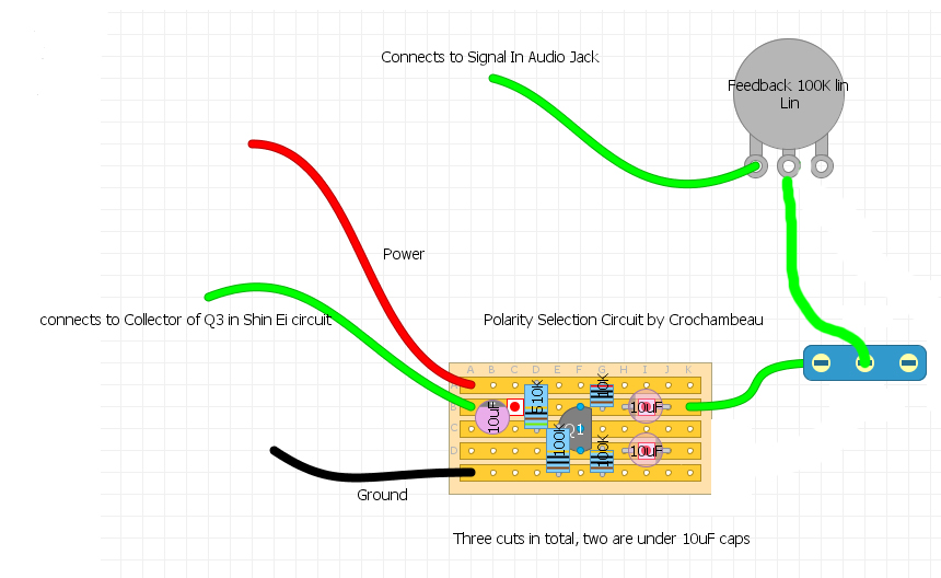
So, in the layout I posted above, where it says "connects to Collector of Q3 in Shin Ei circuit", can that connection be simplified to say, "connects to output of *XX circuit"?
Yep.
I have no idea what that "Polarity Selection Circuit" is supposed to be or do (for example, the negative side of the 10uf on the bottom right isn't connected to anything), but the feedback loop-part seems to be doing the same thing as in the diagram I posted.
Specifically, it's taking the output signal and connecting it to a switch. When the switch is "on", that signal travels to the pot, which allows you to put between 0 and 100k of resistance between the output of Circuit X and the input of Circuit X.
I've breadboarded this setup on a few circuits and the results vary—some circuits give you synth-like oscillation, others do nothing interesting. (I think with the FY-2 it produces a tremolo-like effect.)