Feedback Daughter Board?
|
Hey everyone.
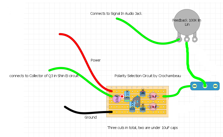
I came across this layout on ILOVEFUZZ site in which a forum member wanted to add a feedback switch to a Shin Ei circuit.  I corrected it from the original layout (I think) for the Shin Ei circuit which is here: http://ilovefuzz.com/viewtopic.php?f=151&t=51980#p1090284 I want to ask the more knowledgeable people here if this feedback addition can be adapted to ANY layout. I see that this specific feedback layout connects to the collector of Q3 on the Shin Ei, is there a general rule for modifying this for any layout? Thanks! |
Re: Feedback Daughter Board?
|
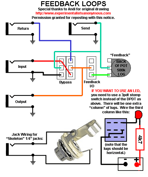
The diagram has the output connected to the input to create a feedback loop, so yes, it can be adapted to any layout.
I believe that's how DBA's Total Sonic Annihilation pedal works. The basic layout for a standalone feedback pedal is something like this: 
|
|
So, in the layout I posted above, where it says "connects to Collector of Q3 in Shin Ei circuit", can that connection be simplified to say, "connects to output of *XX circuit"? I'm just curious if there is a general rule for where the input connection for the feedback daughter board should originate from on *XX circuit...am I making sense?
*(XX is your circuit of choice) |
Re: Feedback Daughter Board?
Yep. I have no idea what that "Polarity Selection Circuit" is supposed to be or do (for example, the negative side of the 10uf on the bottom right isn't connected to anything), but the feedback loop-part seems to be doing the same thing as in the diagram I posted. Specifically, it's taking the output signal and connecting it to a switch. When the switch is "on", that signal travels to the pot, which allows you to put between 0 and 100k of resistance between the output of Circuit X and the input of Circuit X. I've breadboarded this setup on a few circuits and the results vary—some circuits give you synth-like oscillation, others do nothing interesting. (I think with the FY-2 it produces a tremolo-like effect.) |
|
In reply to this post by SeaWitch
I suspect the add on board is to change the polarity/phase of the signal going through the feedback loop so it doesn't cancel the signal. I'll have to give it a try.
|
|
The polarity selection circuit appears to be a polarity switching buffer or similar. You get a separate output for each, which feed the polarity selector switch. The second output appears to have been manually erased from the image.
|
|
OK. I'm an idiot!
Disregard everything I posted above...What I was trying to accomplish is to create a feedback "addition board" that can be added to any effect. I see now that the polarity selection circuit i referenced makes no sense for what I'm trying to accomplish I'm familiar with the standard feedback loop: Effect Output -> 100K pot -> momentary switch -> Effect Input However, I'm just not satisfied with the noise/feedback the standard feedback loop generates. I was thinking that maybe there was a nasty noise generating circuit that I could add to the standard loop....so like this: Effect Output -> noise/feedback circuit ->100K pot -> momentary switch -> Effect Input or this? Effect Input -> noise/feedback circuit ->100K pot -> momentary switch -> Effect Output I want some untameable filth to be generated! Any suggestions or ideas are appreciated...Thanks! |
Re: Feedback Daughter Board?
|
My advice is to look at how existing noise/feedback circuits create their noise/feedback.
So there's the input-to-output feedback in your diagram, the power starve method of the Fuzz Factory, ground starve method of Devi's Hyperion 2, the removal of the 1st feedback cap in Devi's Soda Meiser... etc. Those are all more-or-less daughter board-able, but AFAIK, none are guaranteed to produce "untameable filth" with any and all circuits. And just to be clear, the switch doesn't have to be momentary. |
|
Administrator
|
The input to output feedback will work on pretty much any gain stage as long as the output is in phase with the input.
If the output is out of phase, you can take the “output” from a part of the circuit that is in phase |
«
Return to Open Chat
|
1 view|%1 views
| Free forum by Nabble | Edit this page |

