Fender 2 Button Vibrato/Reverb Footswitch w/LEDs
|
Hey everyone! Thanks for the awesome resource and site. It's so great!
I have a Fender Twin Reverb re-issue with a Vibrato/Reverb Footswitch. I'd like to add LED indicators for the Vibrato/Reverb (using a 9V battery). Does anyone have a layout or plans to do such a thing? I'm getting a bit of conflicting info online. i'd like to use the existing RCA cables, and i'm planning on building a new enclosure. Thanks for any help! |
|
Administrator
|
The amplifier does not provide power through the cable for LEDs, so LEDs would require a power supply or battery
|
|
In reply to this post by SeaWitch
Hi SeaWitch and welcome, always nice to see new faces around
http://tagboardeffects.blogspot.com/2012/02/offboard-wiring.html could be something to work from and adapt as long as the existing footswitch uses latching switches? Otherwise, if it uses non-latching switches and relays then you would probably need to adapt something a little more complex such as this http://tagboardeffects.blogspot.com/search?q=soft+latch As you are intending to use the existing cables and switching method for the amp, then all you need to be able to do is replace the footswitches with the same type (Latching/non-latching) but with more poles (eg use DPDT or 4PDT instead of SPDT) to accomodate the the LED's and any extra circuitry needed to get them to work properly. I'm sure you'll be able to get more effective in depth help from those far more knowlegable than myself, especially those who have dabbled in the dark art of actually building valve amps!! (Check out the open chat section for some sickeningly good examples) but hopefully this will at least help get you started If you can find the schematic for the circuit in question (In this case for the amp and footswitch) and post a link to them, I'm sure it would be greatly appreciated by anyone trying to help  |
|
In reply to this post by Travis
I plan to use a 9V battery, and build a new enclosure...also, i know i need DPDT replacement switches, but I'm unsure how to wire it all up.
I was hoping someone had done this before and could share a nice compact layout and/or some guidance. Thanks for responding! |
|
no idea if anyone has done exactly what you are wanting to do, or even with that specific amp so there probaby isn't a layout yet......if you manage to get sorted perhaps you could knock one up and share it?
Guidance...... Schematics (Only with the legal copyright owners permission of course) or links to them are always good, as are hi res close up photos. Any extra information you can provide is also good as the better the information that is provided, the easier it is for someone to help. Just think of it as the easier you can make it for someone to help, then the more likely you are to get the help you need. Also having a really good read through what has already been posted in the forum can be invaluable in figuring out how to solve a problem for yourself, or at least getting most of the way there. It's surprising how often you will find that the answer you are looking for (Or something very similar) already exists if you care to go looking for it, or you'll learn enough to be able to tackle it yourself. These sites are also packed with an immense amount of useful information so are well worth joining http://www.diystompboxes.com/smfforum http://freestompboxes.org/ |
|
OK! I'm going to gather more info/photos and i'll shout back!
Thanks everyone! |
|
OK. I got busy for a second there....but back on track now.
I attached a couple photos of the footswitch. It uses a TRS cable. Anyone have some insight on how to wire this all up with DPDT switches & LEDs? Thank you! 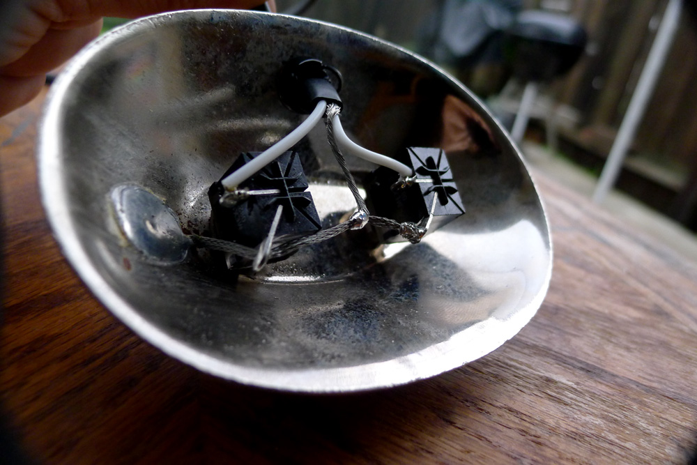 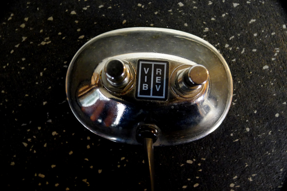 |
|
It's pretty easy to do so, after some googling I drawn this.
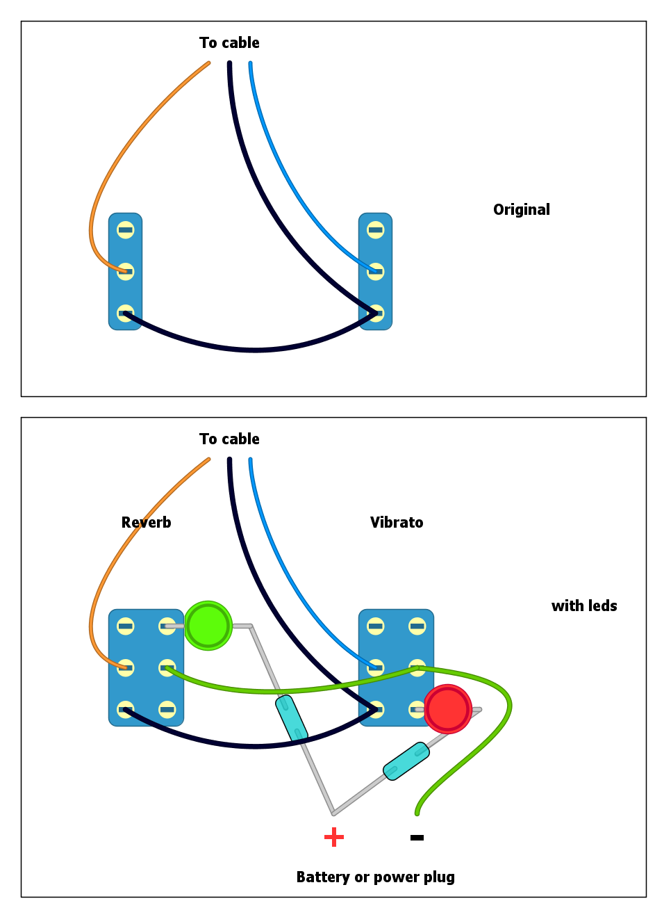 From what I gather "reverb" is on when the wires are not connected, where "vibrato" is on when the wires are connected. If this isn't the case and either led lights up when the effect is off, just move it vertically to the other side. Also, you are using an external power source (battery or supply) so I'm not sure if the two grounds (original nude wire of the switch and the green cable in my drawing) should be connected. I hope someone else can answer that :) |
Re: Fender 2 Button Vibrato/Reverb Footswitch w/LEDs
|
I just built one of these for a Princeton Reverb. I used this drawing I found online. Worked great. A few things to consider:
1. The reverb cable MUST be shielded or you'll get noise on the reverb channel. 2. The PR has RCA jacks on the back. So I bought a shielded RCA to 1/4" TRS cable. So there's still only one cable going to the pedal. 3. I think for battery only you'd want to move both of these + wires to the middle lug of the DC jack, and attach the positive battery snap lead to the right lug. But the switching DC jacks confuse me. 4. Adjust the resistor value for your LEDs. 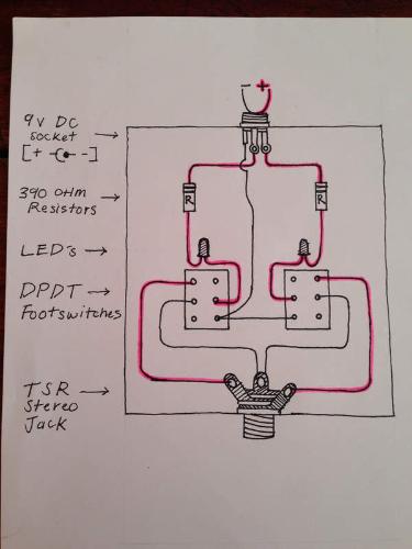
|
|
Thanks everyone!
I put this together last week with help from vigilante397 over at DIY Stompboxes. Original thread here: https://www.diystompboxes.com/smfforum/index.php?topic=120509.0 I attached the layout that worked for me. Works perfect! 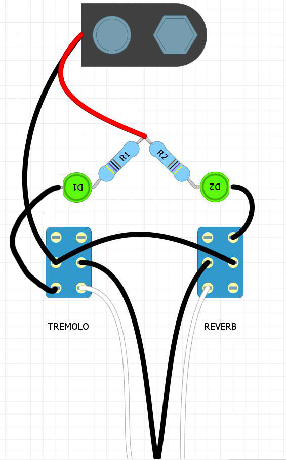 |
«
Return to Requests
|
1 view|%1 views
| Free forum by Nabble | Edit this page |

