First post - First pedal - First Problems!
|
This post was updated on .
They are exactly the same part.
The first listing is for quantity one 8 pin socket only at £0.12 each. The second listing is for quantity fifteen 8 pin sockets for £1.00. I would buy 15 for a Pound - you will need them for other builds! For future reference: 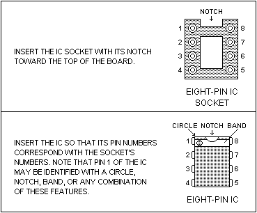 However, please note that you need to look at the IC orientation mark on every layout. The vast majority are with pin 1 (and hence the orientation mark) towards the top of the board, but some are upside down! Always check the orientaion! Fit the chip holder the same way, and fit the chip into the holder the same way too! Finally, don't worry about making mistakes like this - they are standard rookie errors, and they even catch out the most experienced builders on occasion. Courage, mon brave! |
Re: First post - First pedal - First Problems!
|
In reply to this post by odellicour
No it's 12 pence each vs 15 for £1. They're both 8 pins.
aka Dead Eye
|
Re: First post - First pedal - First Problems!
|
Oups ! OK excellent. Le lun. 28 sept. 2015 13:12, vid.sicious [via Guitar FX Layouts] <[hidden email]> a écrit : No it's 12 pence each vs 15 for £1. They're both 8 pins. |
Re: First post - First pedal - First Problems!
|
In reply to this post by Beaker
Hi guys
I received the socket + new IC yesterday. I soldered the socket and installed the new IC this morning and ... no luck :( Still no sound when I engage the pedal |
Re: First post - First pedal - First Problems!
|
We're nearly there
Looking at your last set of pics you're missing the output cap (100nF on top left beside the Volume wires) your signal MUST pass through this cap ignorer to reach the Volume pot....so if no cap....no signal. Put it in and report back. EDIT: That should say top right. I Had the images flipped when viewing 
|
Re: First post - First pedal - First Problems!
|
This post was updated on .
that cap is just for power filtering. it's the 1uf that passes the signal (vol3) and that is ok. in Timmy for example there isn't any 100nf.
the problem must be somewhere else. more photos maybe and voltages... edit: we need photos of the back of your board too. hope you didn't put everything back in the box already...!!! |
Re: First post - First pedal - First Problems!
|
Oops. What the hell was I looking at!!!

|
Re: First post - First pedal - First Problems!
|
OK so it looks ok but is not. Le sam. 3 oct. 2015 11:53, Ciaran Haslett [via Guitar FX Layouts] <[hidden email]> a écrit : Oops. What the hell was I looking at!!! |
Re: First post - First pedal - First Problems!
|
Its time to start eliminating variables I think.
Start with measuring the IC voltages. DMM set to DC volts, ground to a common ground point, Red probe to each leg of IC and record voltage on each leg. BE CAREFUL NOT to short some legs together with the tip of the DMM probe. Report back here. You could also try the following... Check continuity on all your wiring. All grounds are connected together. Each wire isn't broken etc. Wire the boards input and output directly to their jack sockets. This will bypass the switch. If it works then, bad switch. If not, move on.... Build an audio probe like this and trace the signal path from input jack, through the circuit, and output jack. Have a copy of the schematic beside you as you trace. Its much easier to follow signal from a schematic than it is from a layout. If you discover the signal stops at a point it shouldn't you either have a bad component, or there's a short/placement error on that row/area. Its hateful when they don't work first time but I really believe its the non functioning ones that you really learn from. There's little knowledge needed to copy/paste a layout but lots of learning to be got from debugging. So don't get frustrated and feel bad. Take it as a positive to develop your understanding. Post back here with IC voltages etc... |
Re: First post - First pedal - First Problems!
|
OK here we go. Le sam. 3 oct. 2015 17:17, Ciaran Haslett [via Guitar FX Layouts] <[hidden email]> a écrit : Its time to start eliminating variables I think. |
RE: First post - First pedal - First Problems!
|
This post was updated on .
Remember, pins are
1 8 2 7 3 6 4 5
Yeah, 220, 221. Whatever it takes.
|
Re: First post - First pedal - First Problems!
|
Oups Le sam. 3 oct. 2015 18:40, Chris60601 [via Guitar FX Layouts] <[hidden email]> a écrit :
If you reply to this email, your message will be added to the discussion below:
|
Re: First post - First pedal - First Problems!
|
hi there.
are you sure that you've measured your volts the right way? those seem way out of specs 1,2,3,5,6,7 should be round 4,5v 4 should be absolute 0v and 8 should be you supply voltage round 9v (that is the only one that looks right) please take your board off the box. and re-post clear photos of both sides. |
Re: First post - First pedal - First Problems!
|
I put the red/+ probe on the IC leg and the black/ground on the ground part of the imput plug. Correct ? Le dim. 4 oct. 2015 11:31, ξεναγος νεκροπολης [via Guitar FX Layouts] <[hidden email]> a écrit : hi there. |
Re: First post - First pedal - First Problems!
|
yes. you're correct.but if these are the voltages on your pins, then it looks like you give 9v in every pin when you should read round 9v only at pin 8. if we are sure that you're doing this right, then your second ic is probably dead too.
again. i believe that there is a common beginner's mistake here, just like all of us did when we first started.. so post some photos of both sides. from the up side, your build looks perfect and as it should (assuming you've corrected the ic's orientation) your wiring also looks ok as far as i can see. but the back side may give as a clue about what's wrong.you must also get a new ic. good luck |
Re: First post - First pedal - First Problems!
|
Here we go.
First, the soldering is not yet looking beautifull. Practice will hopefully help. I use some tape to isolate the PCB from the pot. OK? 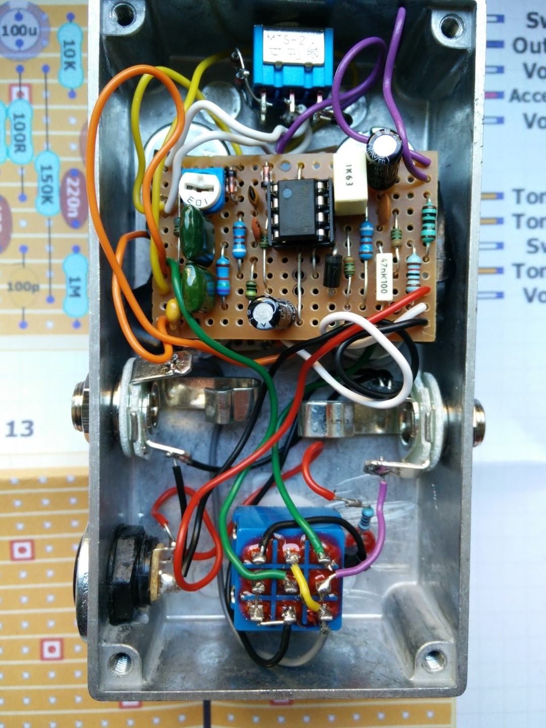 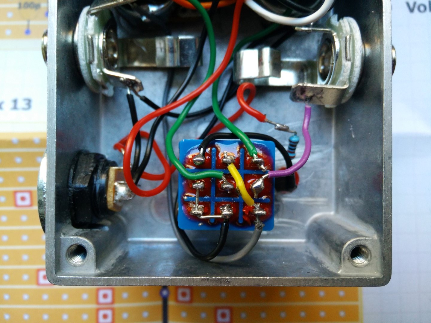 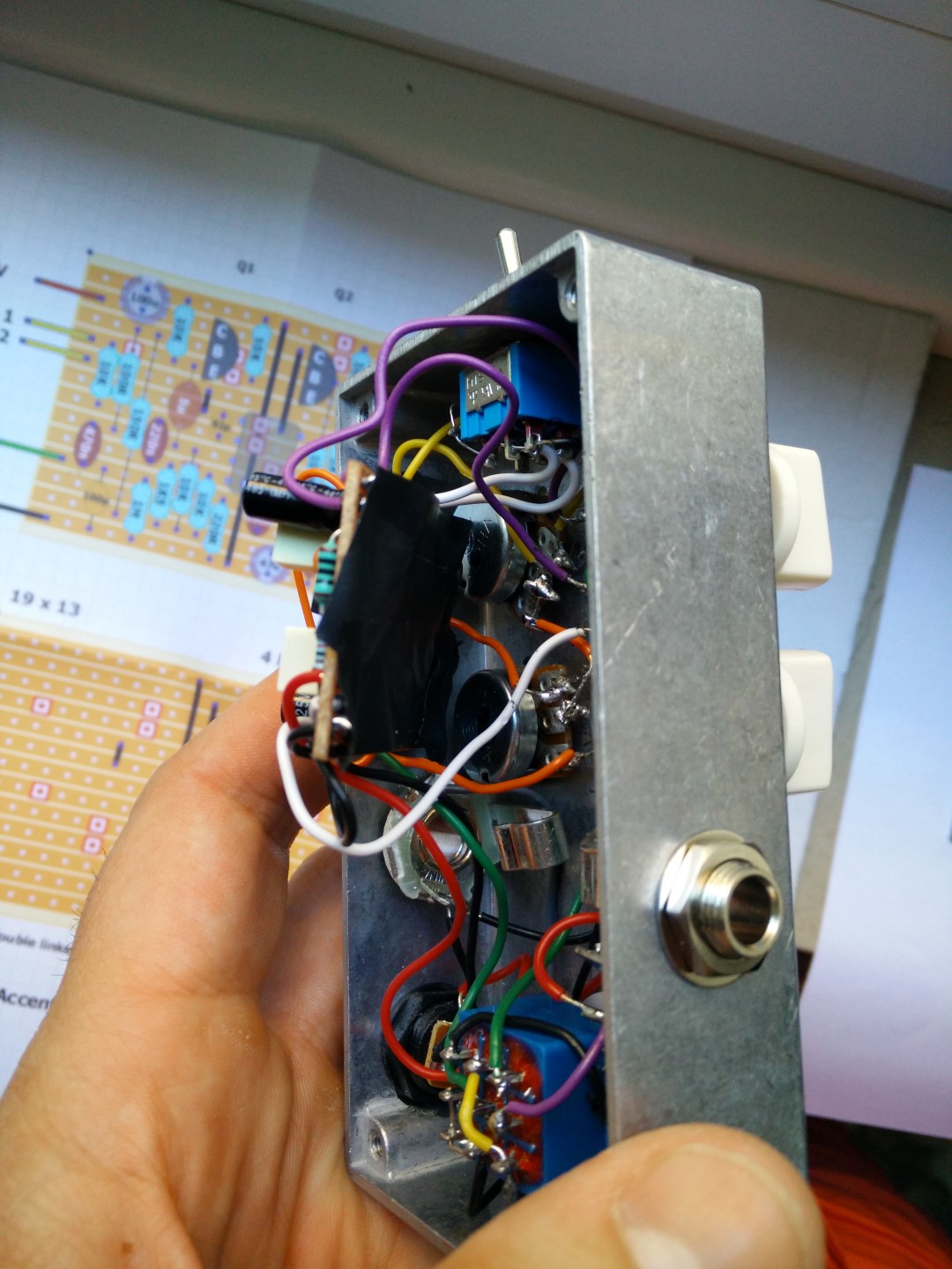 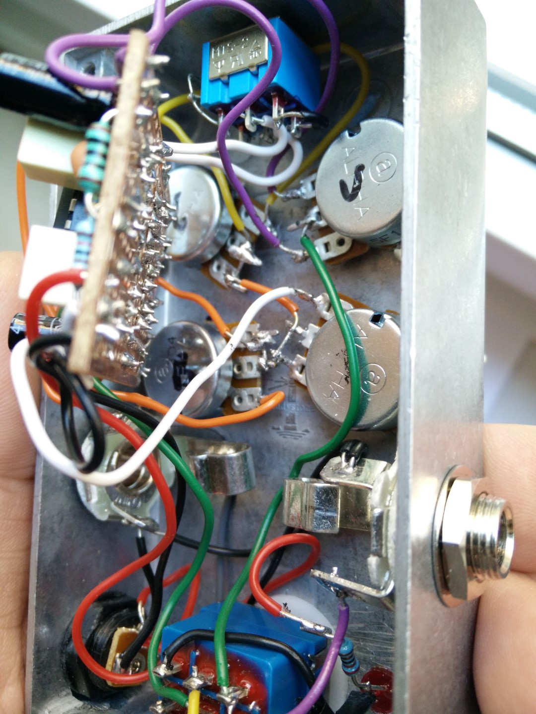 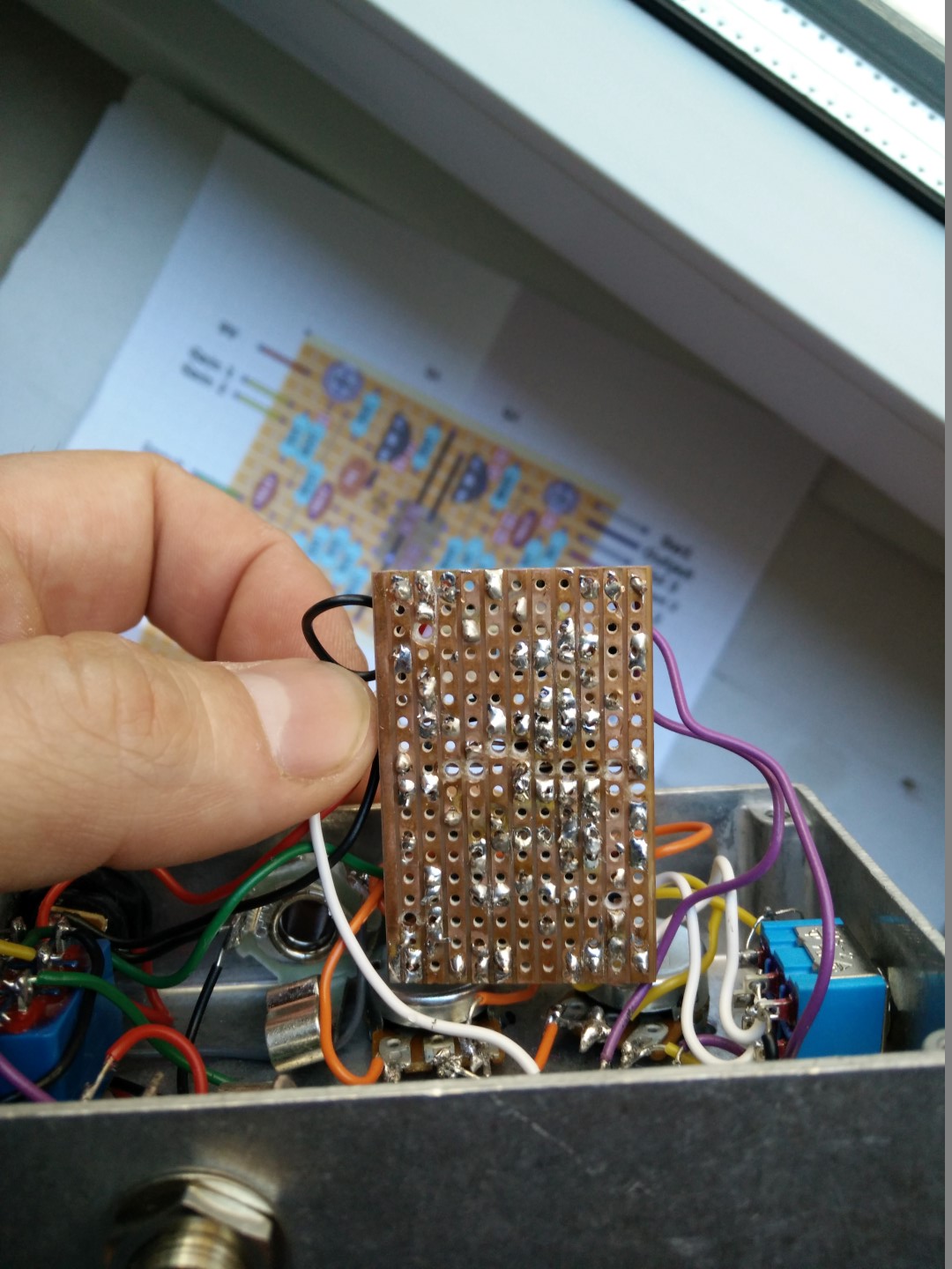 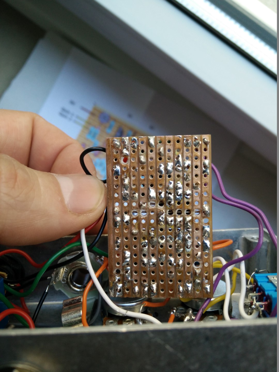 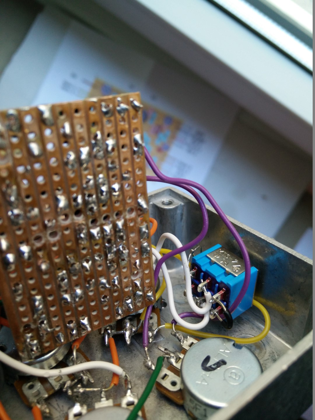 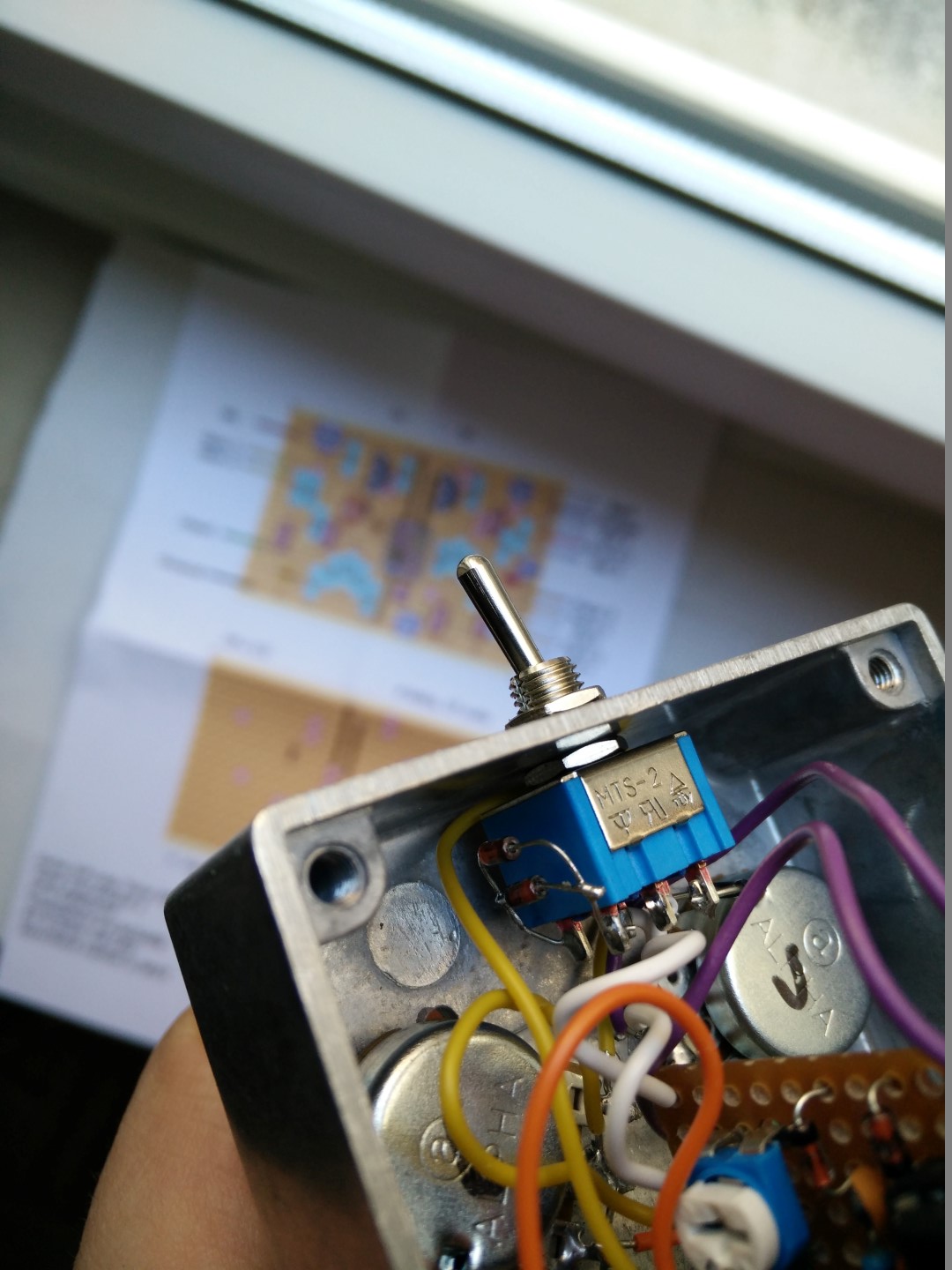
|
Re: First post - First pedal - First Problems!
|
it's obvious that you have to resolder a lot of staff...
your connections must be solid. apply more solder in almost all parts. clear with a knife or a razor all tracks. with your multimeter test everything for unwanted bridges. especially the cuts and links test if all of your ic's legs are really connected to each part that they should. and then be sure of all of these again....and again. i think that the multimeter is you best friend right now! good luck mate! edit:one more thing man. take everything out of the box. that will save you tones of time in debugging. first test that your board works. second box it. |
Re: First post - First pedal - First Problems!
|
OK will do Le dim. 4 oct. 2015 18:12, ξεναγος νεκροπολης [via Guitar FX Layouts] <[hidden email]> a écrit : it's obvious that you have to resolder a lot of staff... |
Re: First post - First pedal - First Problems!
|
In reply to this post by ξεναγος νεκροπολης
OK I resolder everything. Now I have: Le dim. 4 oct. 2015 18:40, Olivier Dellicour <[hidden email]> a écrit :
|
Re: First post - First pedal - First Problems!
|
In reply to this post by ξεναγος νεκροπολης
BTW which software do you guys use to draw the circuit ? Very intuitive. Le dim. 4 oct. 2015 20:10, Olivier Dellicour <[hidden email]> a écrit :
|
| Free forum by Nabble | Edit this page |


