Fulltone 2B - Great Boost with limiter
12


12
|
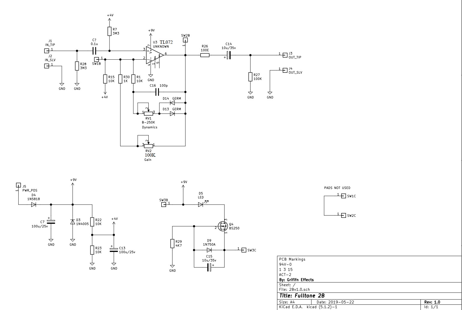
I found this traced Fulltone 2B booster, it's a great boost, it's not TBP it has a buffer when pedal is off and a little limiter/compressor with 2 Germaniun diodes, a nice design.
Can anyone please to do it on stripboard? 
|
|
Do you want it exaclty like that or it's ok if it just true bypass?
I build pedals
|
|
In reply to this post by Claudiog
Hi Claudiog,
U3 should be TL071 and Vref=4.5V Regards, box |
|
Thanks I just found on a web site but thanks for the advise, more info here
https://www.freestompboxes.org/viewtopic.php?f=7&t=29942&p=276377&hilit=fulltone+2b#p276377 |
|
In reply to this post by fx-fidden
I would like exactly like the original, with buffer while is off.
|
|
Ok, I'll try to do it, but I think I need some day.
I build pedals
|
|
In reply to this post by fx-fidden
I reckon without the buffer would kinda defeat its purpose. And personally I think true bypass is heavily overrated. |
|
This post was updated on .
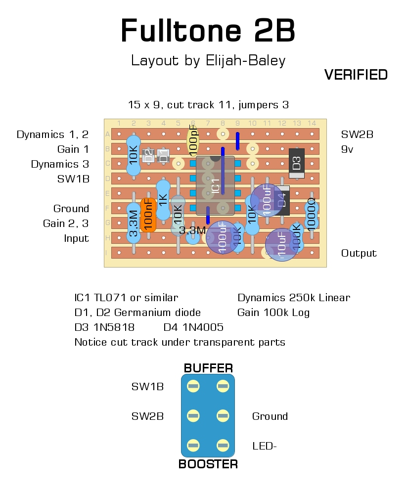
This is my UNVERIFIED layout.
Edit: but probably it's ok.  I omitted just the millennium bypass, I think that BS250 circuit is a sort of millennium bypass or similar switching system that I believe we could leave out without any problem. If I get the wiring the input from the jack goes in the input of the circut, when the boost is engaged the whole circuit works and the DPDT footswitch gives the ground to the negative side of the LED. (For the novice: the positive side of the LED should be connected to the positive lug of the DC jack trhough a resistor between 1k or 4.7k.) In bypass the footswitch connects two points in the circuit getting simply "booster" setted at unity gain: so it's a buffer. The original opamp seems unknown, a TL071 or similar should works fine, the difference should be subtle. The tape of the Gain pot is not specified, I opted for this circuit a log, but a linear will work, too. Maybe you can compare the pot used it with some demo of the original. Tell me if there's any mistake on the layout or someone build it. Edit: I just noticed that I forgot the 1N4005 to the ground in the power supply section. I say that is excessive and not necessary, the 1N5818 (that could be even a 1N5817) will protect the circut enough. Anyway I moved a bit some parts and I have included it. Edit 2: I corrected the orientation of the output cap. And now this is VERIFIED by cjonesplay. 
I build pedals
|
|
This post was updated on .
Wow that was really fast, thank you Fx-fidden, I will build it and let you know!
I just checked following the schematic and looks good, you are right about BS250 it's a kinb of milleniun switch, not necesary as well 1N4005 is protected by 1N5818. thank again! I guess the last resistor form pin 6 (output) is 100R. |
|
You're welcome.
And you are right: that resistor is 100Ω and not 1000Ω.
I build pedals
|
Re: Fulltone 2B - Great Boost with limiter
|
I built this with a TL061 and some 1n60 diodes and it works, but the switch is Boost when flipped up, not Buffer.
Also, the buffer is giving me a lot of volume above unity, which isn’t necessarily a bad thing, but I’d like to know If it’s intentional or not |
|
The two layout are the same but the power supply section is slighlty different.
Anyway, did you build the first or the second layout?
I build pedals
|
|
The output cap is backwards on the second layout.
|
Re: Fulltone 2B - Great Boost with limiter
|
In reply to this post by fx-fidden
I used the 2nd layout and I used a 10u nonpolar Mcc cap on the output, so that’s probably why it worked for me. I’m wondering if using 3.9M instead of 3.3 could cause this issue
|
|
Thanks, induction. The output cap in the second layout is reversed, indeed.
I don't think that 3.9M instead 3.3M cause that issue. I emulated the schematic on my software, and it should work fine. I didn't find any other mistake on the second layout. Probably you did it, but I advice to check your board again with the multimeter for cut tracks, jumpers, position of the wires or eventually unwwanted contatct between stripes (check near the wires soldering, sometimes happend to me). Then the position of the caps adn resistors. If you don't solve, you can try to post here some pictures.
I build pedals
|
Re: Fulltone 2B - Great Boost with limiter
|
Double-checked my work, it’s all good. I built the Cae Boost/Line Driver, too, which is almost the same design and it also increases the volume when only the buffer is on, so I’m thinking it’s just how this design works or there is something wrong with my test rig/cables. Unless you compare the pedal in a TBP FX loop it’s not noticeable. Flip the 10u, reverse buffer/boost labels on the switch, and it’s verified. Thank you for your layout!!
|
|
I'll reverse the output cap 10uF of the second layout, but why I should reverse the switch label?
Maybe we are considering the switch differently that could to cause something wrong in your build that give to you that collateral effect, because the switch make it a buffer, and I can't see how that can give to you a volume boost (is it just a little boost?) I would like to understand this in case there's something wrong in the layout or in your board. I mean when the in the switch you connect individualy the central lugs to the upper lugs, the SW1B and the SW2B are connected each other and the circuit works like a buffer, because all the gain stage consisting by the pots and the diodes are bypassed. At the same time the negative of the LED is disconnected from the ground and can't turn on. When the central lugs are connected to the downer lugs the SW1B and SW2B are disconnected, so the pots control the amount of the boost. At the same time the negative of the LED goes to the ground and make the LED turn on. That's it. Tell me if all this is work for you or I made some mistake, please. 
I build pedals
|
|
This post was updated on .
The switch labels are correct as is.
Maybe cjones is using a toggle switch instead of a stomp switch? In that case, the confusion could be that the position of the switch is the opposite of the lug connections. In other words, when the switch toggle is upward, the common (center) lugs are connected to the bottom lugs. When the switch toggle is downward, the common lugs are connected to the top lugs. That's just how toggle switches work, but it's maybe not intuitive unless you've seen the insides of a toggle switch to understand how they work mechanically. |
|
In reply to this post by cjonesplay
If buffers increase your volume, then yes, I suspect you have an issue with your cables. Is the cable from the pedal to the amp especially long? Or is it going through multiple other pedals between the buffer and the amp? |
Re: Fulltone 2B - Great Boost with limiter
|
I was running it into a PA system until I get my class D amp finished (waiting on the enclosure), so that might have something to do with it. It could be an impedance issue that causes a jump when the buffer is in, as I imagine the buffer ups the Impedance in and lowers it going out. Like I said, it’s probably just me but I wanted to let you know the layout is verified bc I like the limiter section in this, it’s quite useful.
|
«
Return to Open Chat
|
1 view|%1 views
| Free forum by Nabble | Edit this page |

