Hi everyone!
First of all Happy New year (is that allowed still??). Hope everone is well. Saw Zach post some new layouts, awesome to see there are still new things being posted!
I hope someone might be able to help me, since I'm a little over my head. someone I know has a Germanium 4 "Big Muff" with one side not working. I offered to have a look and already said: If it's not an issue with a pot or anything, I probably won't be able to help, but I opened it up anyway. Not sure if anyone is familiar with the circuit? On freestomboxes there is a handdrawn layout I tried to follow.
I have probed a bit and the issue is at the end of the circuit I feel. There is an R26 with clear loud sound, but after that the volume drops considerably.
I took my multimeter out and started measuring. Not sure if its my multimeter, but measuring SMD parts is kind of tough for me. Most of them have a correct reading.
I know this is hard without visuals, so I will show where I'm at :D
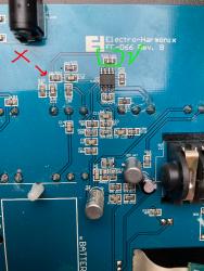
What I dont really understand is: Lots of sound on that green circled R26. Almost no sound at the R27. I marked the point where no sound starts with the cross. I measured that one and it gives a proper 10k reading however. All the resistors do. The R29 on the left of that (underneath the arrow), I can't get a reading.
Could a resistor failing in this position cause a volume drop? Or should I be looking at the capacitors in the path from this point on? I have no experience with replacing smd, so I'm trying to rule out as much as I can :D
Hope someone knows if I can be more precise in my hunt!
The drawn schematic on the (public thread) would be here:
https://www.freestompboxes.org/viewtopic.php?t=20612

