Got a problem with the rangemaster
|
Hi guys,
I built the Dallas Rangemaster TB with tone switch : http://tagboardeffects.blogspot.fr/2014/02/dallas-rangemaster-pnp-negative-ground.html My build does not work, I have no sound. The strange thing is that when I test the tranny with my DCA55 when plugged in its socket in the circuit, it reads LED or diode If I remove it from the socket, then it reads PNP Ge as it should... An other thing when I look at the layout, it seems to me that if i omit the in and out cap as they are now switchable on the 4p3t, input wire coming from pole B should move 2 rows up to connect the base right ? Well, I tried this but it still doesn't work No problem with the ICL I get -9V were it should Any idea ? |
|
I'm trying to figure out what's wrong and I can't find the issue
The thing that puzzles me is this problem with the transistor I tried 4 or 5 with the same result How can it read PNP Ge and then diode when I plug it in the socket ? The leg that doesn't read is the collector, no matter the pinout in the socket 
|
|
Administrator
|
|
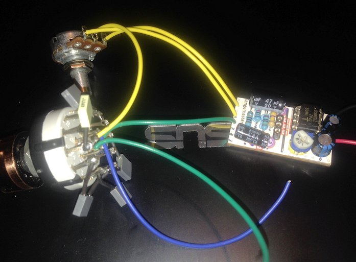
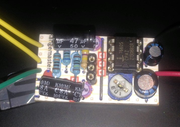
Here is a picture :
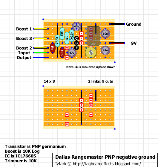
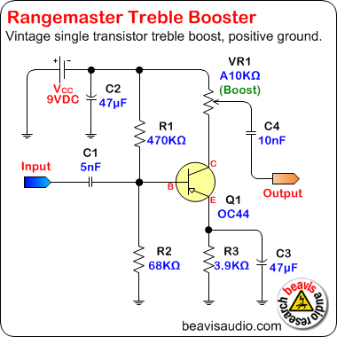
  And the layout  The 3p4t wiring is ok i verified it with my multimeter The only difference with my build is that I move the input 2 rows up now that the 5n cap is no more on the board. I'll have to bring back the in to its initial position and add a link in place of the 5n cap to keep the 1M pulldown resistor into the circuit Again, voltages are good, -9V on IC pin 5 and -6.7V on the collector with the trimmer set at 3k |
|
Administrator
|
I my be we wrong but I think if you put the wiring back to normal, just replace the input and output caps with a jumper and see what happens. I think that the way it's wired now something is put right. For instance the 1M resistor to input to ground is not connected anymore, bu you just mentioned that. Also, the 100k resistor at the output isn't connected either anymore.
|
|
Yes, you're right but those 2 resistors are just pulldown so they have no inpact on the audio signal. Mark added them on his layout, they are not on the original schematic.
So the problem must be somewhere else 
|
|
In reply to this post by alltrax74
That's not quite right. That would put the pulldown on the wrong side of the input cap, in parallel with the 68k. You'll want to keep the input where it is. If you want to use the pulldown, you'll have to run an extra wire from the input at the tone switch or the stomp switch to where the input is on the original layout. The same idea goes for the output pulldown. To keep it on the outside of the output cap, you'll have to run an extra wire from either the tone or the stomp switch. It's not too surprising that you get strange readings from components in-circuit. The surrounding components provide connectivity that violates the assumptions of the measurement. Trust the readings from the components when they are out of the circuit. That said, I have no idea why your circuit isn't working. Maybe post a photo of the other side of the board. |
|
Strangely I just took a look at the range master I built from the same layout, also with the switchable caps and noticed that I have bypassed the pulldown resistors without realising. However the circuit works fine without them. I also built it with switchable transistors since I couldn't decide which sounded best an oc44 or oc71 so I have both, fortunately they both biased correctly at the same trimmer position. That said I can't see any issues, perhaps knife the back of the board if you haven't already.
|
|
In reply to this post by induction
That's right induction, pulldown resistors are on the wrong side on the in/out caps
I'll wire them from the jacks to the stomp I already verified all the usual suspects. Next step will be to pull the probe out of the drawer (for such a simple circuit, damn !) Anyway, thanks guys for you input, I appreciate 
|
|
It may be a cold solder joint. Get your iron hot and reflow all the joints. This happened to me once - I had no sound and it turned out to be a cold solder joint at a key junction in the circuit.
|
Re: Got a problem with the rangemaster
|
In reply to this post by alltrax74
is the ic upside down?... doesnt that mean it goes on the otherside of the board idk im a noob . also i love how you have the layout on top of the strip board how did you do that?..
|
|
This IC is upside down on the layout (you can see the dot which indicates the orientation)
Very simple, I printed the layout on a sticker. It is very helpfull as you don't have anymore to count rows and columns, and you avoid the risk of component misplacement. I always do this now BTW I still didn't take the time to find what is wrong. Actually I don't have time at all for pedal building these weeks, but I'll have to get back to it |
Re: Got a problem with the rangemaster
|
I think we need to see the other side
|
«
Return to Open Chat
|
1 view|%1 views
| Free forum by Nabble | Edit this page |

