Gravity wave wiring

classic Classic list List threaded Threaded
11 messages Options
Reply | Threaded
Open this post in threaded view
|

Gravity wave wiring

stinkypu
Hi im trying to put this together https://tagboardeffects.blogspot.com/2016/02/madbean-gravity-wave-earthquaker.html

Im Just not sure how to wire the shape 2-3 and anim 2-3

Ive seen a few builds but cant make out how the pots are wired
Reply | Threaded
Open this post in threaded view
|

Re: Gravity wave wiring

rocket88
Administrator
Not sure if this is one of your first builds, but if it is I would start with something simpler. In any event to answer your question, if you look at the layout or any layout for that matter that has it 2 lugs listed for the same wire that means those lugs are connected and have a single wire going to that point on the board.
Reply | Threaded
Open this post in threaded view
|

Re: Gravity wave wiring

Marbles
In reply to this post by stinkypu
Yeah that's a tricky build :)

But as rocket said, it just means that the wire coming out of that row is connected to shape 2 AND shape 3.

You can do that with 2 wires coming from that spot, 1 wire going to shape 2 and  one wire going to shape 3.

Another (better and easier) way is to have 1 wire from that spot going to shape 2 and also have a wire going from shape 2 to 3. As long as they are connected.

Also pay attention to the description where it mentions some lugs going to ground!
Reply | Threaded
Open this post in threaded view
|

Re: Gravity wave wiring

stinkypu
Hi  thanks for replying its one of my first builds

just so far they have all had separate markings for the lugs ,i can do this when its paint by numbers stuff but ask my brain to engage after a day of looking at a picture then a board and back i couldnt figure it out.

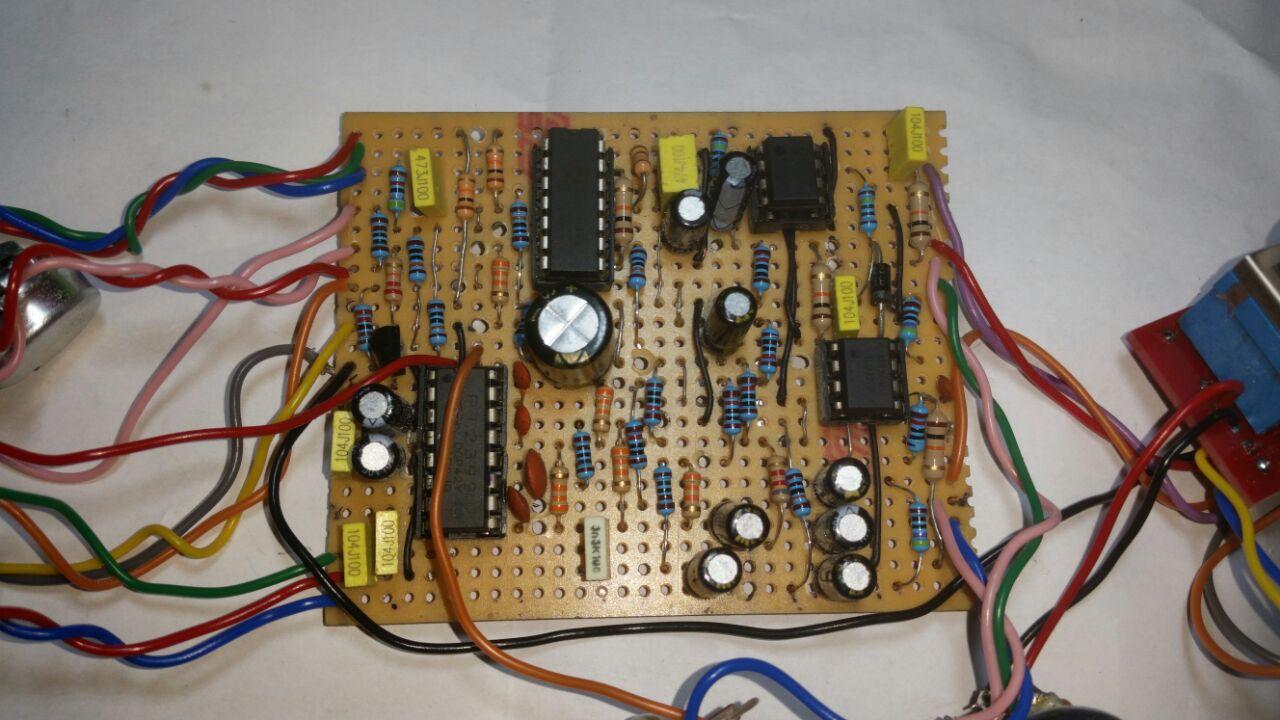
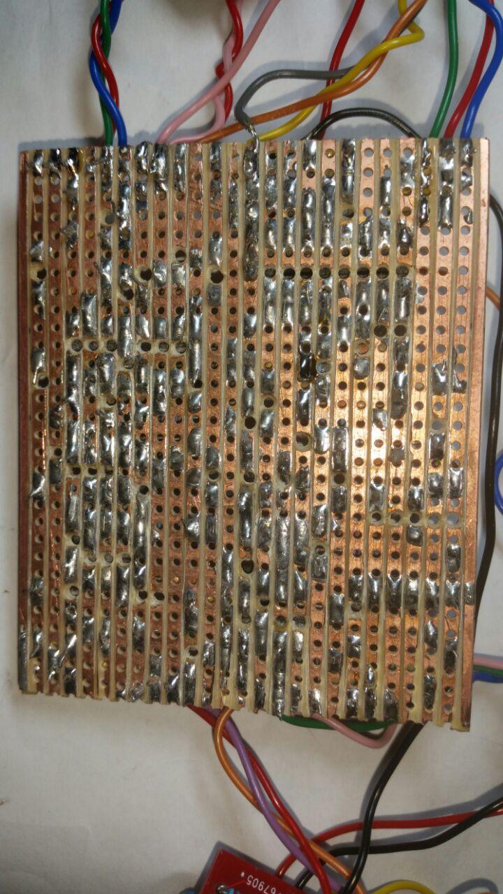
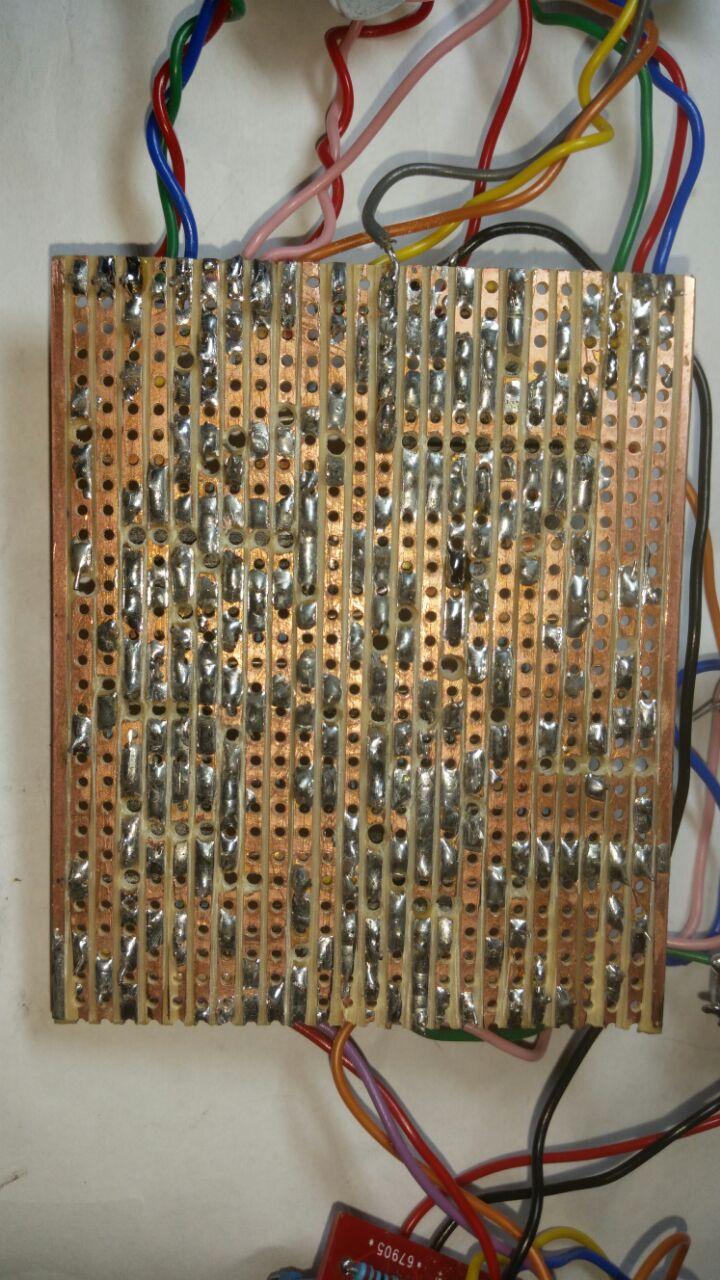
I think i have this one pretty much finished i just need to check the wires and anywhere the copper track may have lifted ive been using more jumpers to get around this


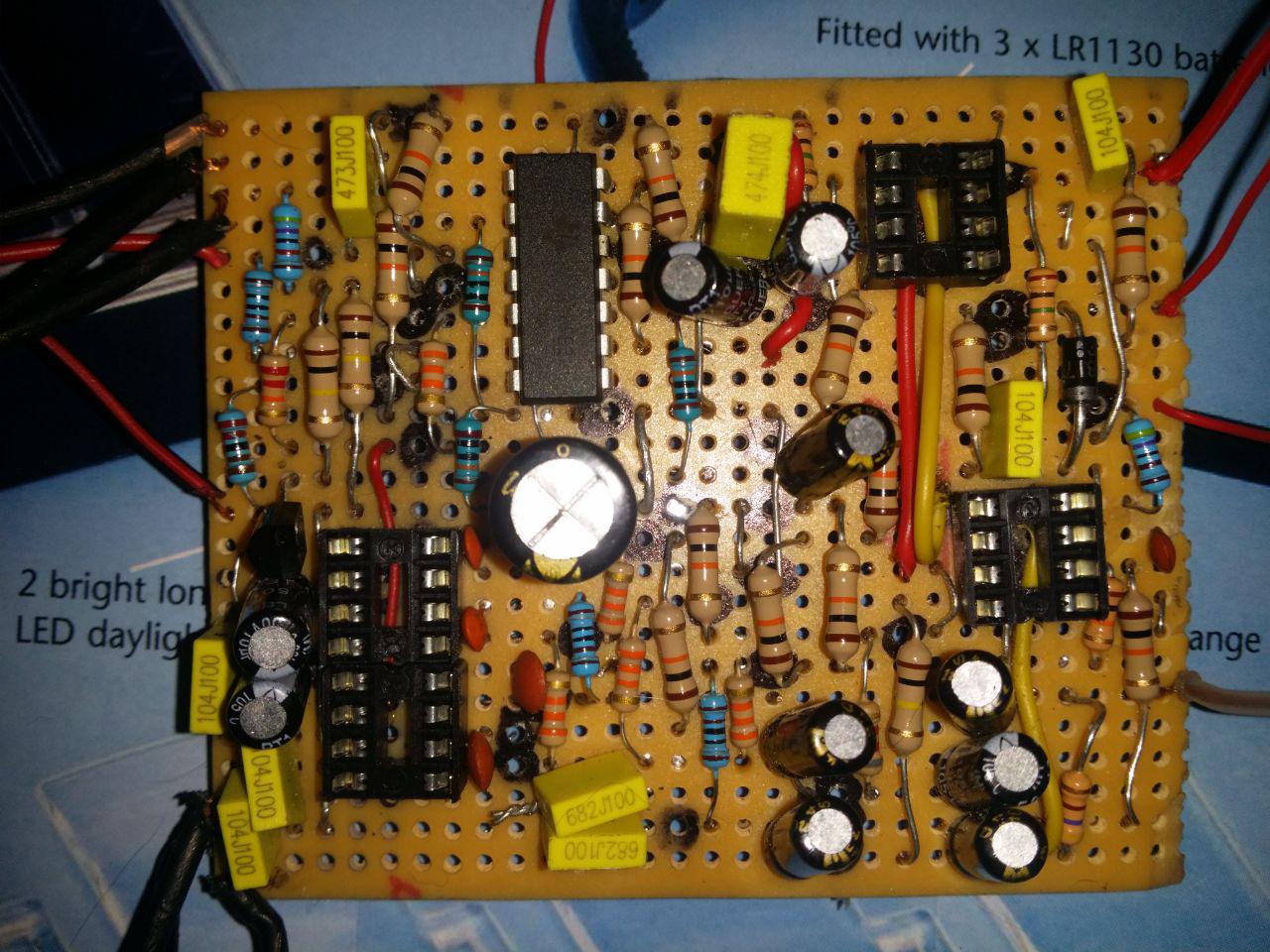
also i used 2 6.8nf in series for the 3n3 and didnt have any spare sockets for the lm324 but ive spare lm324 lol

Thanks again I'll try to finish this later
Reply | Threaded
Open this post in threaded view
|

Re: Gravity wave wiring

stinkypu
In reply to this post by Marbles
Hi Again I've been reading over this a few times and trying to make sense of whats going on .

When you say theres a few ways of doing it would i be able to run one wire then a jumper between lugs 2 and 3?

And can anyone help me understand whats going on here - i understand the variable resistor and wiper whats going on in respect of the lugs just not whats going on here :S when one point on the board is going to two lugs (am i missing the obvious i.e. these lugs are going to ground and and thats what the pot is varying?)

I apologize if its a bit of basic question just im trying to understand more of whats happening instead of just putting things together and crossing my fingers :D
Reply | Threaded
Open this post in threaded view
|

Re: Gravity wave wiring

Marbles
Hey!

Yes, I usually connect them by a snipped off bit of a resistor and let the wire go to lug 2. So: 1 wire from the board goes to lug 2 and there is a jumper between lugs 2 and 3.

There is more info on pots on this page:

http://beavisaudio.com/techpages/pots/

Not sure if it's applicable in this situation, but the following explanation is given:


But what happens if the potentiometer fails for some reason (age, poor quality, dirty, etc.)? If the wiper (which is the rotating part of the component and probably most prone to failure) shorts out, it will let the full amount of signal through. By attaching lug 1 to lug 2, we are building in a fail-safe. This ensures that the circuit is never completely open--there will always be some resistive path in case the wiper goes south.
Reply | Threaded
Open this post in threaded view
|

Re: Gravity wave wiring

stinkypu
Hello :) i had square eyes when i replied i seen wire wire wire and had a brain fart when i read it again i figured a wire - jumper its the same thing im just being stupid lol

I have a bag of resistor legs for the very purpose :D i tried to use them for the jumpers on this but theres a few longer ones i used some wire for it.

And thanks for posting the info i couldnt make sense of why you would run the two wires to the same row

Ive spent the last few hours trying to add the wires and debug Im not asking for help .... YET!!!! lol at the minute the issues are of my own making i missed a link (it fell out i had them all in i swear ;) ) im sure i seen it on the floor all in a nice u shape :D Something in the bottom left (cap and jumper was out of place)

Then fixing these led to new solder bridges ,burnt tracks and then i thought ive fixed those jumpered over the burnt tracks made sure i didnt jumper over a cut mistakenly  ill start adding the wires - this has been the frustrating thing every time i have them all wired one wire breaks I fix that go hmm ill plug it in see where i am oooohhh lights are working ahhhh another broken wire and repeat a few times get to where i think im ready again and another broken wire gotta laugh ffs

im going to order new hookup wire i think (i know and dont want to admit it) ive bought the wrong kind or poor quality wire its adding to my woes all im doing is flipping the board with the pot attached to the wire not swinging it by the pot lol either that or im buying terminals soldering them to everything and jumper leads lol
Reply | Threaded
Open this post in threaded view
|

Re: Gravity wave wiring

stinkypu
Hello again guys , I took some time off from pedal building and decided to try this one again!!

so i started with a fresh vero board and ordered some new components

not having much luck with this one ffs :)


so ive got the board populated went over the gaps with a hacksaw and stanley knife to be on the safe side
 at the minute im getting the same signal out as whats going in ( its been a while since i tried this last so some things may have fallen in to a memory hole and i dont remember what i spent days doing last time lol )

one thing i noticed after reading my previous posts was that i had only done a jumper on one of the pots i have found out that what happened is thayt i folded my print out and missed shape 2-3 being jumpered i will fix that tomorrow .

i did remember that the voltage readings can help so i took those before i gave up tonight

i got some funny readings from lm324 with it fluctuating so if i post 2 sets of values for one pin its the lowest then the highest

so heres what i got so far

lm324
1. 1.69-7.2         8. no reading 0
2. 3.96               9. 4.4
3. 4.22               10.4.33
4. 9.29               11. 0
5. 3.09               12 4.33
6. 5.74               13.4.55
7. no reading 0   14. 3.19>5.74

pt2399
1. 4.92             9 to 16 all read 2.46
2. 2.45
3. 0
4. 0
5. 2.59
6 2.39
7. 0.74
8. 0.82

The next values are for the tl072 i'll call the one higher up the board 1 and the lower one 2

tl072 number 1

1. 4.7    5. 9.29          
2. 4.7    6. 4.7
3. 4.67  7.  4.7
4. 0       8. 2.35


tl072 number 2

1. 4.69   5. 9.29          
2. 4.69   6. 4.7
3. 4.7     7.  4.7
4. 0        8. 4.7

So all im sure of at the minute is i havent connected shape 2-3 the rest i was fairly confident i had got right and didnt have any misplaced cuts ,jumpers or components

I hope you can help and that youre all doing well at this crazy time in the world

Cheers

Stinkypu
Reply | Threaded
Open this post in threaded view
|

Re: Gravity wave wiring

stinkypu
Ive had no luck and checked the board over a few times now i cant see anything i have missed or put in the wrong place Ive added some photos in the hope one of you guys can spot something ive done wrong :)

Theres a few  ground wires from the pots that i have placed in the row that ground is on in case youre wondering what those *extra wires are :)


Reply | Threaded
Open this post in threaded view
|

Re: Gravity wave wiring

Kalimna
I don't know how helpful this will be, but I've had a go at building one of these. It sort of works.
Ive built around 20 pedals now, and Im only *just* getting them to work first time.
The things you haven't mentioned that *might* be an issue are electrolytics being the wrong way around, faulty IC's, misplaced jumpers/off board wiring.
To be honest (and I did this with a Ross Phaser build 3 times!), I would start over with a new vero, with fresh components (they aren't expensive). You have the off-board wiring, so no need to change that (unless you have the 1-2-3 lugs around the wrong way).
See this build as a learning point, and try to make the soldering a bit neater, the component legs a little shorter etc.
The fundamentals of this layout are no different, construction-wise, than a tiny Naga Viper (also on this forum). It's just more soldering. And consequently *much* harder to locate and fix errors.
So, that's what I would do.
Good luck either way.

Adam
Reply | Threaded
Open this post in threaded view
|

Re: Gravity wave wiring

stinkypu
Hi Adam thanks for the  reply

Ive built this 3 seperate times lol and never had any luck ive built others and only had the normal nut behind the wheel issues (i was building one for a friend and he needed a 9v battery and only told me this after i built and tested the thing after adding the battery snap i managed to the hold the battery on the wrong contacts and fried the whole thing replaced the caps and the ic still nothing built it from scratch again nothing turned out the second build i misplaced a resisitor in to the wrong row d'oh)

for this build i decicided to buy a pcb and then make sure the ics are working and then for the others i bought a small component tester which is quite handy its able to do transistors capacitors resisitors and diodes and was only about £7 the other thing which i have since added to my bits box is a pair of side cutters you can really get a good low cut with them i was using a pair of snips before that were ok but not the right tool for the job :)

Once i can summon the enthusiasm to get back to this one i'll post back and update where i went wrong :)

Cheers