Gristleizer

classic Classic list List threaded Threaded
19 messages Options
Reply | Threaded
Open this post in threaded view
|

Gristleizer

gigi
Hello, i will be  happy to  have  a good  vero  of the Gristleizer.
From this  link

http://gaussmarkov.net/wordpress/circuits/gristleizer/

REgards
Reply | Threaded
Open this post in threaded view
|

Re: Gristleizer

Jopn
The end of the build document has a vero layout, but the format is ugly as sin.

http://gaussmarkov.net/layouts/gristle/gristle-project.pdf
Q: Why is a drummer like a scud missile?
A: Both are offensive and inaccurate.
Reply | Threaded
Open this post in threaded view
|

Re: Gristleizer

dexxyy
yeah and it`s 33x23 with standing resistors. 5 ic`s, 2 tranny`s and 4 trimmers there is no way this is going to meet Mark & Miro`s criteria so I seriously doubt you`ll see this anytime soon.
If it wasn't for this website I would definitely have a life.
Reply | Threaded
Open this post in threaded view
|

Re: Gristleizer

johnk
I drew one up that's a bit smaller than their vero (34x20) but that's still pretty huge! IMO, the wiring is much more organized (all on the two ends of the vero). mine also includes a 7660S voltage inverter to get the needed + & -9V. I also made mine with the depth and bias controls externally. I just need to go over it a few more times to triple check everything before i build it.
Reply | Threaded
Open this post in threaded view
|

Re: Gristleizer

johnk
okay, I've gone over it a bunch of times so I think that it'll work, but I prefer to build it and verify it before I post the vero.

I used this schematic tro draw up the vero:

http://johnkvintageguitars.homestead.com/Effects/others/Gristleizer/gristle-schem.png
Reply | Threaded
Open this post in threaded view
|

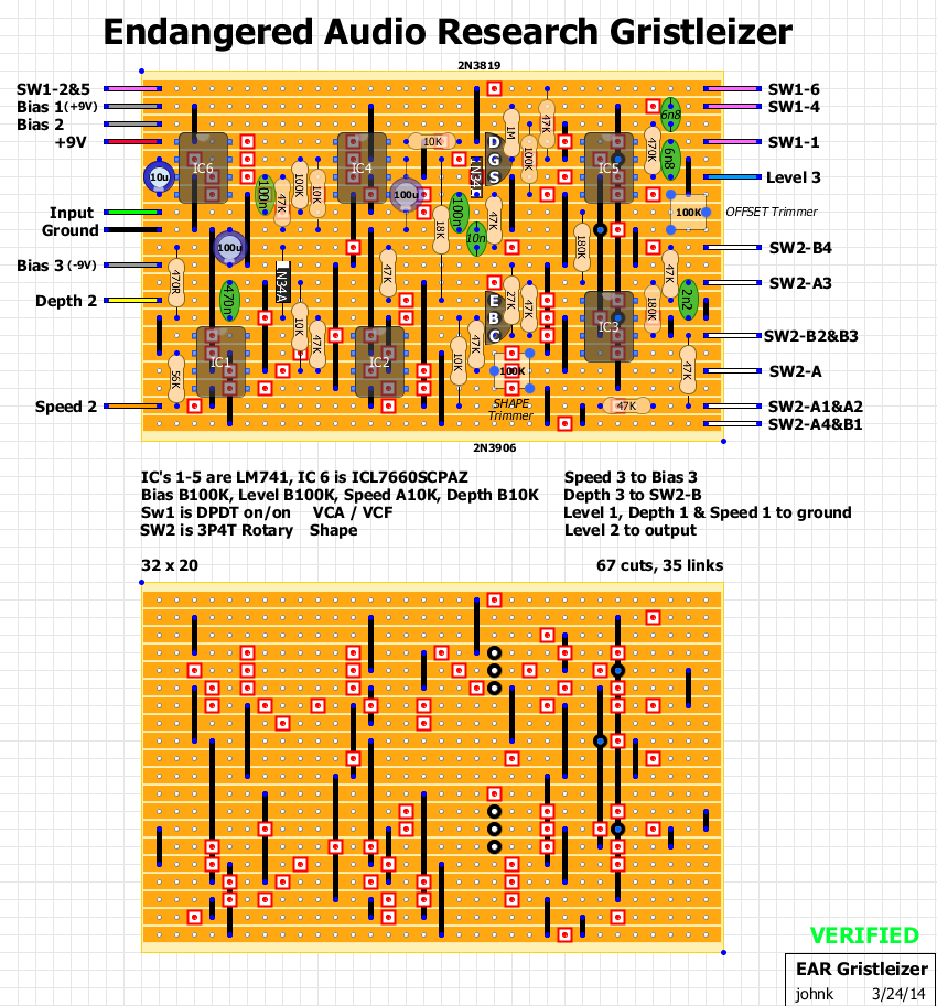
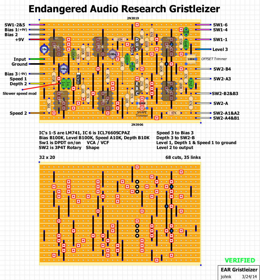
Gristleizer Vero layout VERIFIED

johnk
This post was updated on .
I just updated the layout, and built it so it's now verified.  I was also able to make it a little smaller at 32 x 20 with no stand up resistors (it does have a zillion cuts and links though at 67 cuts and 35 links!)


if you copied the one that I posted earlier today, disregard it and use this newest one.

Reply | Threaded
Open this post in threaded view
|

Re: Gristleizer Vero layout

IvIark
Administrator
Excellent, and no standing resistors!
Reply | Threaded
Open this post in threaded view
|

Re: Gristleizer Vero layout

johnk
updated and verified.
Reply | Threaded
Open this post in threaded view
|

Re: Gristleizer Vero layout

Alex
This post was updated on .
Fantastic job as usual!
Is your build ticking or noisy as some people reported about this pedal on FSB?
I've seen Mictester modified schematics but I don't know how it works:
http://freestompboxes.org/viewtopic.php?f=1&t=760&p=235230&hilit=gristleizer#p235230
Reply | Threaded
Open this post in threaded view
|

Re: Gristleizer Vero layout

johnk
thanks!
and nope. the ticking is barely noticeable, if at all. If you use TL061's for the LFO (IC1, IC2) it even has less ticking than the LM741's did, but they weren't bad at all.
having a scope it makes calibrating the shape control a lot easier.
I also made the speed control able to go a lot slower by replacing the 470n with two 1u's in parallel:

Reply | Threaded
Open this post in threaded view
|

Re: Gristleizer Vero layout

Alex
Cool!
You could even add a switch with 470nF and 2uF caps.
I'll definitely build one.
I want to make a layout for Mictester version and if it comes out smaller enough I'll build one and compare it.
Thanks again!
Reply | Threaded
Open this post in threaded view
|

Re: Gristleizer Vero layout

johnk
albru80 wrote
Cool!
You could even add a switch with 470nF and 2uF caps.
you could, but I don't see any reason to. the slowest setting wasn't all that slow set fully CCW, and with the two 1u's the fastest speed is still super fast.
Reply | Threaded
Open this post in threaded view
|

Re: Gristleizer Vero layout

Alex
No worthed then.
Any possible subs for the FET?
Reply | Threaded
Open this post in threaded view
|

Re: Gristleizer Vero layout

johnk
almost any Jfet will work. I've heard that you can use a J113 or2N5457. just mind the pinout since they're not the same as a 2N3819.
Reply | Threaded
Open this post in threaded view
|

Re: Gristleizer Vero layout

Alex
In reply to this post by johnk
Hi John,
It may be a stupid question but shouldn't the 47K resistor going to Sw2-B4 be connected to pin 6 instead of pin 8?
Reply | Threaded
Open this post in threaded view
|

Re: Gristleizer Vero layout

johnk
albru80 wrote
Hi John,
It may be a stupid question but shouldn't the 47K resistor going to Sw2-B4 be connected to pin 6 instead of pin 8?
it actually does connect to pin 6. I forgot to move the link one column to the right.
Reply | Threaded
Open this post in threaded view
|

Re: Gristleizer Vero layout

Alex
I've finished Mictester version and it works.
I've found some 2n3819 and I compare them to the 2n5457 & MPF102.
The 2n5457 were doing nothing and the MPF102 was the closest one.
I've used the 2n3819 at the end cause it sounded different.
I've done a new layout with the right pinout
Reply | Threaded
Open this post in threaded view
|

Re: Gristleizer

jarvennn
In reply to this post by gigi
Hello. Very nice layout.

What if I would like to add a flickering LED to show the speed of the vca/vcf?

Thank you!!
Reply | Threaded
Open this post in threaded view
|

Re: Gristleizer Vero layout

tomeunknown
In reply to this post by johnk
Hello! Here’s some build info if anyone is ever interested.

I just built johnk’s version and it’s great.. made some adjustments.

Changed the 100k opamp feedback resistor to 470k for heaps more output and gain. This is great for a variety of reasons inc making the bias pot more useful in vca mode.

Changed the input cap from 100n to 15n.. it was way too thick and muddy for me.

Changed the 6.8n filter cap to 62n … the filter sweep via the bias pot is way more useful and way less shrill and ear piercing.

Cheers!