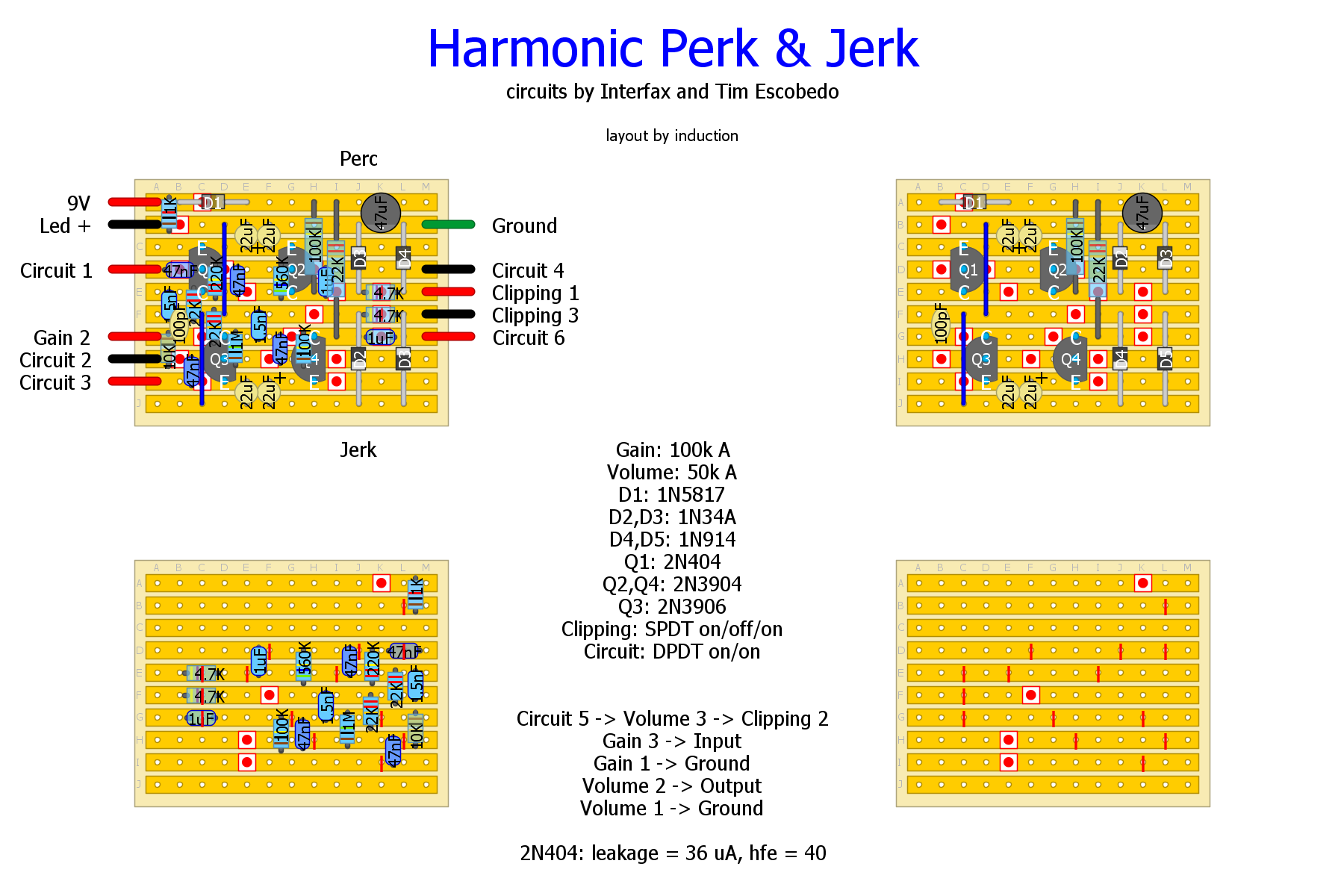
Harmonic Perk & Jerk SMD/TH hybrid
|
This post was updated on .
If I could only have one dirt pedal, it would be this one, no question. My favorite by a long shot.
Two circuits on one board: Select between the Interfax Harmonic Percolator and the Escobedo Harmonic Jerkulator, and Si, Ge, or no clipping diodes. I started with the values in the linked schematics and fooled around on the breadboard until I optimized each circuit to my preference. Neither circuit is exactly stock, but there are lots of different Percolator schems around, so that doesn't mean much. The topology of the circuit is what makes this thing do what it does, and I haven't changed that. The Percolator needs a low gain PNP germanium, while the Jerkulator wants low gain Si PNP. I adjusted caps and resistors to taste, feel free to do the same. I also added a 10k input resistor to kill the (very loud) buzz when you turn your guitar volume all the way off. I didn't have any 47u tantalums, so I used pairs of 22u tants. You can use 47u if you have them. Legend has it that it really wants tants in that spot, so who am I to argue. I can't swear it will sound any different with regular electrolytics, though. Both circuits are very sensitive to input volume, and the volume knob cleanup trick works so well that I probably won't put a Gain control on mine, I'll just control it from the guitar. Depending on input volume it goes from tight clean-but-dirty overdrive, through distortion territory and into splattery spongy fuzz. The Si and Ge circuits sound pretty similar at low input volume, but diverge quite a bit at full gain. The clipping options give more or less volume and a slightly different flavor. It's loud as all hell with no clipping diodes. You might find the Ge circuit quieter than the Si circuit, even with Ge clipping at full input volume. That surprised me, but didn't bother me much. This one is verified by me, and I can't get enough of it.    |
|
I'm soooo building this. I had a lot of fun building Jimi's photonic Jeurgulator so this is going on my list for sure. |
|
In reply to this post by induction
Awesome, thanks induction. Next on the build list.
"Red velvet lines the black box"
|
|
Thanks a lot, I built PJP Juergulator too, amazing sounds I get out of this so this sure will be built too. Thank you!
|
|
In reply to this post by induction
What size box do you recommend?? I managed to get the Perc into a 1590B but it was a fiddle, and this has two extra switches. I might play it safe and go for a 1590B |
|
Mine fits in a 1590B with plenty of room to spare. I think it would fit in a 1590A, especially if you forgo the gain pot. I never use A's though, so I'm no expert.
|
|
What can i use as a sub for the 1n419's Would a D9 germanium diode work ok? |
First, let me apologize for the typo. The correct diodes are 1N914's, but any garden-variety Si will do. The layout has been updated to correct the mistake. That being said, I make my layouts as references for my builds. I mod almost every circuit I build, and I document everything to prepare for the inevitable future time when I forget what changes I made. So the layout just shows what I actually built. But obviously you should feel free to modify the circuit to your heart's desire, just as I did. The clipping switch gives you Si (1N914), Ge (1N34A), or no diode clipping. You can swap the diodes as you please and the circuit will still operate, but the clipping flavor will change. You can replace either set of diodes with your favorite Ge or Si clipping diodes, or you can design your own clipping switch: led's vs. Ge's; 1 Ge and 1 Si antiparallel vs. 1 Si and 1 led antiparallel for two flavors of asymmetric clipping; symmetric vs. asymmetric, etc. It's entirely a question of what suits you best. |
|
In reply to this post by Hozy31
Built this today. Got one side working the other not quite. Haven't debugged yet but the side thats working properly sounds really good. Debug the other side tomorrow. Need to watch football soon.
Thanks for the layout Induction.
"Red velvet lines the black box"
|
I had the exact same problem. couldn't figure out where it was wrong either. Did you manage to get it fixed Hozy??? |
|
Never got round to getting back to it. Still sitting in my debug pile. If you have any luck let me know.
"Red velvet lines the black box"
|
Got mine working over the weekend, I'd missed a smd cap on the Perc side. The Jerc side is kinda noisy and has a strange thin, trebley quality to it, I don't think I'm experienced enough with this kinda thing to explain properly. I'll get it boxed up anyway and see if the interference is still there, perhaps I'll need to shield the input and output. |
|
Hey Induction, Just a quick query. I was going to try to lay this out on vero without the smd's because I just can't get on with them and I'm not too fussy about the size. There are two 1.5nf caps on the layout which run to ground and which don't appear on the schematic. can you tell me what they do and perhaps show me where they might be added onto the schematic. Awesome pedal by the way. |
|
There are a great variety of schematics for the harmonic percolator out there, and those caps are present on most of them, but are not on the ones I linked to just by chance. They are on Madbean's Pepperspray, and a few others. I don't recall exactly what the impact of that cap is, but I remember that the effect is very small. Small enough that it might not be noticeable at all for your rig. Thinking back, I seem to remember that it reduced high frequency hash a little bit, and made the circuits sound a little smoother (which is not to say either one sounds smooth at all, because they definitely don't), but that could be a false memory or a flashback or something, so take it with a grain or two of salt.
Just remember that most of the (many, many) schematics that I consulted when making mine disagreed with each other, and then I tweaked them even more on the breadboard. The components on the vero represent what I thought sounded best with my rig and the transistors I had on hand, and probably don't agree 100% with any other schematic out there. You might want to consider adjusting yours to taste as well. If you're going to the trouble of making a new vero, I recommend breadboarding it first so that you know what you're getting before you build it. These circuits have a tendency to sound a little bit different with each build, even when you use the same component values, so I built mine with the specific components I used on the breadboard, except for the SMD. Good luck with yours, I'm glad you like the circuit. |
Thanks for taking the trouble to respond, i was thinking of making up a few pcb's if the cost isn't prohibitive. I guess that the basic layout will remain the same regardless of the values and i can breadboard to determine what is best. |
|
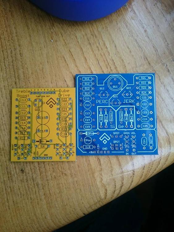
Got a few pcb's made up (mostly to teach myself eagle) and they arrived this week. I managed to screw the GND pads up a bit but there's an easy fix.  The other board is a valvecaster with a switchable treble boost Thanks for the help induction. |
|
They look really good - fantastic first effort. What's up with the ground pads, they look fine to me.
|
They aren't connected to ground  Basically i thought that the ground pad would automatically connect to the ground net, but alas not. So i've had to resort to scrapping off a little of the solder mask and bridging the pads with a bit of solder. Lesson learned for next time. |
|
In reply to this post by PMowdes
Hi
Are the Peak DCA55 still available, Maplin @ 19.99 I'm from Australia, Best Price is $122.00 (around 76 GBP) Anybody in the UK help out a fellow builder ? Cheers music6000 |
«
Return to Hybrid Layouts (Through-Hole/SMD)
|
1 view|%1 views
| Free forum by Nabble | Edit this page |


