Loading... |
Reply to author |
Edit post |
Move post |
Delete this post |
Delete this post and replies |
Change post date |
Print post |
Permalink |
Raw mail |
![]() ![]() ![]() ![]() ![]() ![]() ![]() |
9 posts
|
Hi everyone,
I was wondering if this looked right to you? I took the layout from robrobinette's page (under solid state spring reverb here: https://robrobinette.com/Compact_Reverb.htm#Solid_State_Spring_Reverb) I just needed to make the circuit board smaller, so this is my attempt at laying it out on stripboard. Thanks for the help! ![]() |
Loading... |
Reply to author |
Edit post |
Move post |
Delete this post |
Delete this post and replies |
Change post date |
Print post |
Permalink |
Raw mail |
![]() ![]() ![]() ![]() ![]() ![]() ![]() |
170 posts
|
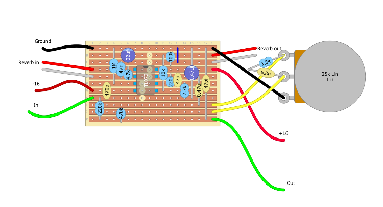
Hey tvas22 - That looks like it should work. However you are stretching a 47pF cap over a long distance which it should make if it's silver mica - which would actually be a good idea! - but some ceramics might not make it.
Here is a smaller layout which avoids standing resistors, which a lot of folks prefer I guess it might be slightly more robust, although millions of Maxon pedals might disagree. :-) I also put the pot mounted parts on the board. You might want to check the voltages required to make sure the components you use don't fry. Seeing as the circuit uses a TL072 I guess you'll be ok with 50V but don't take my word for it. ![]() 
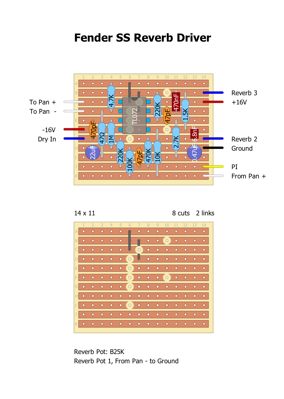
I haven't built this so it obviously isn't verified. There may be mistakes. It looks ok to me though. :-) |
Loading... |
Reply to author |
Edit post |
Move post |
Delete this post |
Delete this post and replies |
Change post date |
Print post |
Permalink |
Raw mail |
![]() ![]() ![]() ![]() ![]() ![]() ![]() |
9 posts
|
Hey, that’s fantastic thank you. Yours looks great, I will use that. It was my first time laying something out so I figured it could be better.
Hopefully I’ll have tested the circuit out sometime in the next couple of months so I’ll let you know if it can be verified. I also did the power supply board, which takes 40-60vac and provides the -/+16v. I am planning on using 50vac... will this be OK on stripboard? |
Loading... |
Reply to author |
Edit post |
Move post |
Delete this post |
Delete this post and replies |
Change post date |
Print post |
Permalink |
Raw mail |
![]() ![]() ![]() ![]() ![]() ![]() ![]() |
170 posts
|
I'm not the right person to ask, but I suspect it would depend on current rather than voltage and i doubt that the current draw would be massive. My guess is that stripboard would be ok but I would recommend checking with someone more knowledgable than me.
|
Loading... |
Reply to author |
Edit post |
Move post |
Delete this post |
Delete this post and replies |
Change post date |
Print post |
Permalink |
Raw mail |
![]() ![]() ![]() ![]() ![]() ![]() ![]() |
9 posts
|
Ah, OK. I will run that by an amp building forum at some point and see what they recommend.
Thanks again! I really appreciate it. |
Loading... |
Reply to author |
Edit post |
Move post |
Delete this post |
Delete this post and replies |
Change post date |
Print post |
Permalink |
Raw mail |
![]() ![]() ![]() ![]() ![]() ![]() ![]() |
9 posts
|
I finally got around to building this - your layout can be verified. It sounds pretty good!
|
Loading... |
Reply to author |
Edit post |
Move post |
Delete this post |
Delete this post and replies |
Change post date |
Print post |
Permalink |
Raw mail |
![]() ![]() ![]() ![]() ![]() ![]() ![]() |
170 posts
|
Glad I could help!
|
Loading... |
Reply to author |
Edit post |
Move post |
Delete this post |
Delete this post and replies |
Change post date |
Print post |
Permalink |
Raw mail |
![]() ![]() ![]() ![]() ![]() ![]() ![]() |
9 posts
|
Thanks again. You don’t by any chance have any ideas about how to increase the volume of it do you? I installed it on a switch, I would say there’s about a 30-40% drop in volume with it engaged.
|
Loading... |
Reply to author |
Edit post |
Move post |
Delete this post |
Delete this post and replies |
Change post date |
Print post |
Permalink |
Raw mail |
![]() ![]() ![]() ![]() ![]() ![]() ![]() |
3 posts
|
In reply to this post by tvas22
Not a problem here works with one of those cheap chinese tanks I bought a few years ago. Thanks guys
|
Loading... |
Reply to author |
Edit post |
Move post |
Delete this post |
Delete this post and replies |
Change post date |
Print post |
Permalink |
Raw mail |
![]() ![]() ![]() ![]() ![]() ![]() ![]() |
6 posts
|
This post was updated on Apr 21, 2020; 10:35pm.
Is this circuit suitable for use as a pedal or is it only for in between the preamp and power stages in an amp?
If the latter how would I adapt it for use in front of an amp (like an outboard reverb unit or pedal)? |
Loading... |
Reply to author |
Edit post |
Move post |
Delete this post |
Delete this post and replies |
Change post date |
Print post |
Permalink |
Raw mail |
![]() ![]() ![]() ![]() ![]() ![]() ![]() |
9 posts
|
I really have no idea - the tank is a full sized reverb tank though, so even if you did build it into a pedal you would need to find somewhere to mount that.
I think it would be worth giving a go, though. It is just a solid state tank driver stage and a recovery stage, and then the wet signal is just blended back into the dry. I can't see why it wouldn't, in principle, work - if you run into impedance issues you could try playing around with buffers before or after. |
Loading... |
Reply to author |
Edit post |
Move post |
Delete this post |
Delete this post and replies |
Change post date |
Print post |
Permalink |
Raw mail |
![]() ![]() ![]() ![]() ![]() ![]() ![]() |
6 posts
|
Could those buffers you speak of be something like an lpb1 at both end to bring the signal level back up or am I getting the wrong idea?
|
Loading... |
Reply to author |
Edit post |
Move post |
Delete this post |
Delete this post and replies |
Change post date |
Print post |
Permalink |
Raw mail |
![]() ![]() ![]() ![]() ![]() ![]() ![]() |
9 posts
|
Maybe, I’m really not sure if it would work but I think it might be fun to experiment. I installed a super hard on boost before the reverb which did help a little, and then there was another gain stage after it in the amp.
|
Loading... |
Reply to author |
Edit post |
Move post |
Delete this post |
Delete this post and replies |
Change post date |
Print post |
Permalink |
Raw mail |
![]() ![]() ![]() ![]() ![]() ![]() ![]() |
6 posts
|
Thanks, I plan on using this as the last thing in my chain before it enters the amp so hopefully it could work.
How can I find out what the input and output impedances of this circuit are? I need a high input and low output right? |
Loading... |
Reply to author |
Edit post |
Move post |
Delete this post |
Delete this post and replies |
Change post date |
Print post |
Permalink |
Raw mail |
![]() ![]() ![]() ![]() ![]() ![]() ![]() |
9 posts
|
Honestly, I have no idea what the impedances are here - I actually ran into impedance issues, which is why I installed the boost/buffer before it. When I was trying to figure out the issue (huge volume drop, tone suck etc) I figured it was probably an impedance issue, and I spent a long time trying to calculate it (or find someone else that could help me to calculate it) and I didn’t end up getting anywhere.
I’m not sure if the dry signal ‘sees’ the 1M to ground or if it only ‘sees’ the 220k resistor. I tried bypassing the 220k and it made no difference to how the circuit functioned, however. That’s when I gave up and installed the buffer. I think either way it is going to be an experiment. It’s quite a nice sounding reverb in the amp, so it might end up being decent. I also built the Wampler Faux Spring Reverb though, and that sounds nice through the front end (although it’s belton brick rather than spring). |
Free forum by Nabble | Edit this page |