How to read schematics

12
12

|
The value of voltage divider resistors is usually a balance between input impedance and thermal noise. The specifics vary for different devices and topologies, but the general idea is that the input impedance of a subcircuit involving an active device (an op-amp, for example) will depend very strongly on the parallel value of those resistors. Thus, if you want the input impedance to be high, you want to use high-value resistors. On the other hand, thermal noise increases with resistance, so making the resistors too high can add noise, which can be a big problem in a high gain circuit. The usual approach to this balancing act is called 'low-noise biasing' (sometimes called 'noiseless biasing' but I think that's a bit optimistic). The trick is to use 10k resistors (actually, the rule of thumb I've seen is 2k total resistance per volt, but 10k gets you very close) to form the Vref divider, then connect the Vref node to the signal/device input node through a large value (1Meg or so) resistor. Additionally, a large cap (10u or higher) is connected between the Vref node and ground. This shunts any thermal or PSU noise to ground before it reaches the device input. The biasing current running through the large resistor is very small (most of the current runs through the 10k biasing resistors) so the thermal noise due to the large resistor is negligible, and the input resistance is determined by the value of the large resistor. This way, you get both high input impedance and low thermal noise. It's important that the cap be connected on the other side of the large resistor from the signal, otherwise the cap will shunt high frequencies to ground and the signal will get dark. I wouldn't count on any given pedal designer following these rules, though. The Klon buffer, for instance, uses a 1Meg resistor for the big one, but then uses 100k resistors in the divider. This will reduce current consumption somewhat, but at the expense of higher thermal noise. He uses a 47u to reduce Vref noise, though, so you probably can't tell the difference. You usually have a lot of leeway with voltage dividers. Another concern with resistor values in a voltage divider is the effect of load resistance. In my university electronics courses (I'm a physicist, not an EE, so my formal electronics education is pretty limited), the professor used an analogy comparing resistors in a voltage divider to springs. Connect two identical stiff springs together and stretch them across the room. Now do the same for less stiff springs. The junction of both sets of springs will sit in the same place. But if you try to move the junction point one way or the other, it will be harder to do with the stiff springs. A voltage divider is the same way. Two 1k resistors in series between 9V and ground will give you a 4.5V node at the center just the same as two 1Meg resistors will. But if you attach a load to the 4.5V node, the input resistance of that load is in parallel with the lower resistor, which can drag the voltage down. (Vocabulary note: low input impedance = heavy load; high input impedance = light load.) Higher value resistors make the voltage divider stiffer, so it is less likely to be perturbed by loading. Note that when you use low-noise biasing, the large resistor is in series with the load, so the minimum input resistance is 1Meg, or whatever value you used there. This maintains the stiffness of the divider while allowing you to use smaller biasing resistors. With pedals, you usually (but not always) know what the load on any given divider is going to be, so voltage divider stiffness isn't discussed as much as the other points above. It's still a good thing to keep in mind when designing circuits, though. It can matter when the impedance of some subcircuit depends on the signal. Another way to solve this problem is to use low value resistors, and then buffer Vref. |

|
|
In reply to this post by induction
This is a fantastic thread.
For someone who's just about climbing up the food chain from amoeba, it's really great to see theory with a bias towards effects. I know a cap does capacitance and a resistor resists the same wherever they are applied [in electronics] and I get what various electronic components do to an electical current but for me, understanding the various 'stages' of the audio signal path is where I hit the black box principle of understanding. Thanks to other articles and posts [mostly] on here, and specifically IVIark's layout guide, I am starting to understand a little more about what happens to the guitar signal in that black box. Now, all those naughty IC's and Trannies kicking it around and diodes making it turn left, make a lot more sense, although I'm still way off really understanding the workings of even the most simple circuit in its entirety. So I hear a lot about 'stages'. Input stage, gain stage, output stage, tone stage, deadwood stage. What do they all mean and why are they important? How does my input actually work its way through and get added to by stages? Or is this even what actually happens? I can figure it out up to a point but my ignorance overwhelmes me :( I think of these circuits in a modular way. Put simplistically, I am thinking that the input is passed to various stages (modules?) within the circuit, which will then apply its MoJo Secret HoBo MonKey Joose then pass it along to the next one until it becomes output. I also think that in some circuits, along the way, the signal gets split and rejoined through various 'Monkey MoJo Modules' to alter the characterstics. Am I on the right track or am I stupid? (which is a natural trait :)) If anyone has any information about the common stages (I don't even know if this is even a real concept?), how they work and how they affect the input, that would be great. I know this might seem like a really odd question, but these stages or stacks or whatever they are seem to be glossed over amongst people who know this stuff. I read, 'just add a tone stack' or 'it's in the gain stage'. I guess I'd just like to be able to understand what's going on a little better without trawling through tons of dry theory and reverse engineering schematics/layouts until my eyes fall out :p Thanks for all the help you guys give for nothing and thanks for making it really easy for your average moron (me) to access this stuff and actually make things that work. I'll shut up now... |
|
|
Ed, you are bang on. The "stages" correspond exactly to your idea of "modules".
As you say, the trick is recognising those stages on a schematic. Sometimes it is fairly straightforward, sometimes, especially when ICs are involved, it's not. That's when I start to struggle This is the BEST expanation of what is going on (in graphic form), in a pedal I have come across: 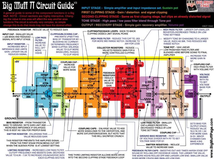 And the link to the whole page: http://www.kitrae.net/music/big_muff_guts.html I hope this helps - it did me! |
|
|
In reply to this post by induction
Thanks again, Induction! Very interesting reading. You are touching on a fundamental subject that I'd like to nail once and for all, and that is the concept of a "heavy" versus "light" load. In fact, the concept of "loading" is an interesting one, as it gets to the whole point that the AC ** current ** is as import as the actual AC voltages being generated by a stomp box circuit (which we tend to focus on).
My view is as follows. A load is "heavy" if, to maintain a given voltage, you need more current from the circuit. And since power = V*I, it means more power, or in the case of our little 9V batteries, draining the battery faster (not a good thing). It follows that if the effective impedance of the thing you're connecting your effect circuit to at its output (e.g. your amp) is LOW, then it will take more current from your effect signal to drive the amp. If you don't have enough current, then the voltage will drop off and the signal will be reduced. Conversely, a "light" load (= HIGH impedance) does not require as much current to maintain the signal. Any comments appreciated. 
|
|
|
In reply to this post by Beaker
Thanks Beaker. It's nice to know I'm kinda getting it :)
I'll have a read of that link, thanks. I suppose it's just a matter of time and I'm still really new to this, but I want to know it all NOW!!!! The layout guide from IVIark in the link above was really good for me. I know it's for schematics -> layout, but because he added each section bit by bit, it made it really easy to PacMan around the maze, so to speak. Thanks to that article, I went from: This...  ...to this...  ...to this!!! All in one read :) 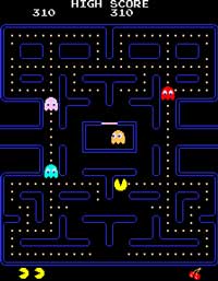
|
|
|
In reply to this post by Ed Nice
Stages: See, we have these little circuit snippets (aka building blocks) that perform certain functions, and we use them over and over. It's very rare that anyone invents a new building block, we just combine the ones that we know in different orders and combinations. As your second-to-last paragraph (which is a very good explanation, by the way) states, each building block has an input and output; they have their way with the signal, then pass it on to the next one. A 'stage' is just what we call one of these building blocks. We have gain stages (common emitter amplifier, common source amplifier, SRPP/mu-amp, inverting and non-inverting op-amp, etc.), buffer stages (emitter follower, source follower, etc.), LFO (low-frequency oscillator) stages, filters (low-pass, high-pass, twin-T, tone stacks), and so on. The trick of pedal designing is to learn these basic building blocks - what they do, how they do it, common pitfalls and solutions - and then stitch them together to make bigger circuits that bend the signal to your will. Once you learn what the building blocks look like (Wikipedia has good articles on most of them, and you can follow the related articles links at the bottom for days at a time; there are also literally thousands of websites that discuss them and lay them out systematically, though not usually with a pedal-focus) you will soon be able to identify them by sight. Then reading schematics becomes very simple. It's just familiarity, nothing too exotic. Anybody can do it. I always recommend buying a breadboard and a bunch of components, then joining FSB and DIYSB, and reading every thread back to the beginning, building what you read about as you go. Best pedal electronics education you can get. Careful of the Deadwood stage, though. No law at all in Deadwood. |
|
|
Thanks Induction. :) I really appreciate the time you take to answer questions.
I have read quite a lot about this stuff from the internet, but it either completely dry, brain numbing [for a non-electronics person] tedium or scanty waffle with little actual substance and links to more of the same. My reason for asking this [I'm so glad it hasn't turned out to be a super dumb question, BTW!] on here, is that, well it did seem a good opportunity to ask in an appropriate thread and you guys are so helpful but also because you are really, really fucking good at this stuff and I know I'll get the answer without any BS or messing around and for the most part, the answer will contain the answer to the next three questions I didn't even know I needed to ask yet! :) If you ever visit Manchester, the beers are on me! |
|
|
In reply to this post by induction
Thanks again, Induction.
Obviously I did get very lucky, or like Columbus I stumbled upon something amazing without realizing what I had done. But yes, I got a tremendous gain boost AND I got the treble I felt the circuit needed. I am very happy with the result. So, I will need to time to digest what you wrote - but I will definitely look into it. |
|
|
This is a fantastic discussion -
I just wanted to point something out for the people like me who are also still learning, once again referring to Mark's layout guide:  This is a split schematic, but even more important, you have to notice some important abbreviations: it uses a voltage divider - coming off the junction of the two 10k resistors - and the result is 50% of the original V+. So, like most voltage dividers we see here, the original 9v gets cut in half to 4.5v. Well, in this schematic, the symbol V+ is used for the original 9v, but coming off the voltage divider a new symbol is introduced, Vr (short for Vref). Instead of drawing out all the connections, the designer just drew the bottom portion by abbreviating Vr as a reference starting point to the voltage input - and we need to keep in mind it is 4.5v. I am just saying that this is not the common schematic, and I don't think I would have noticed how it was done if Mark had not pointed it out in his text. ALSO: another Beavis graphic explanation of the basics of an overdrive (to add to what Beaker gave us up above) is here: http://www.beavisaudio.com/techpages/HIW/HIW.png Also - Frank offered up this article on the same topic: http://www.generalguitargadgets.com/how-to-build-it/technical-help/articles/design-distortion/ All three are great references for understanding these circuits. |
|
|
Ok, so now split schematics have been mentioned, is there an easy way to identify how the different parts of a split schematic stitch together?
The one posted above is easy to see, but some others really have me scratching my head! |
|
|
Beaker - good question and nice contribution up above. I would like to see an example of the type of split schematic you are referring to, because if it confuses you it would probably also confuse me.
|
|
|
In reply to this post by induction
In reply to the sound difference of my "gain/tone" pot - here is a sample. Original circuit first, then after the mod second...
https://soundcloud.com/paulmotter/liquid-sunshine |
|
|
In reply to this post by motterpaul
Like this:
http://www.runoffgroove.com/ginger.html When I first built this, I worked it out by tracing the signal path through the PCB. Now I have forgotten, and can't visualise the join. This is typical of the kind of schems I have problems with. |
|
|
Yup - interesting. I read someplace B+ is just an old way to say "Battery +"
On a wild guess, I am going say this is "upside down" in that the 9v should be on top, as we were just taught. But that A (coming off the gain pot on the "in section") goes to A going into 10k and Q3 in the lower half. note: Edited for clarity. It is confusing to visualize what it would look like after you combine them, though, I agree. |
|
|
In reply to this post by induction
huge thanks to you induction for your original post and follow up here.
most electronics theory stuff is just a quantum leap too far for me (being used to building-by-numbers from the layouts here with only a tiny bit of insight into what i'm doing) but you've pitched your original post here so as to make me feel that if i stick with it and work through the bits i don't understand i can grasp something really worth knowing. have saved to print out and keep around for lucid moments. also wanted to say the images others have posted re tonestacks and hi/lo pass filters and circuit stages have helped too. sometimes my head spins with text alone, but i can grasp an abstract concept if supported by a diagram. so a team effort. a+ |
|
|
This post was updated on .
Keeping the post alive - I thought this was interesting. I just realized I really need to learn how to dissect an op-amp. I was just reading about op-amps in schematics and I ran across this line:
"In some schematics, the Vcc(+) (power) and Vcc(-) ground will not be shown. This does not mean you don't have to connect these pins, you DO have to; the schematic writer is assuming you already know this.." ummm.... yeah, I knew that. By the way - this is where I read that and it is a great FAQ on just about everything having to do with reading schematics: http://www.diystompboxes.com/wiki/index.php?title=Frequently_Asked_Questions_(DIY_FAQ) |
«
Return to Open Chat
|
1 view|%1 views
| Free forum by Nabble | Edit this page |