How to read schematics

12
12

|
I have seen lots of posts where people state that they cannot read schematics, and lots of people asking for sources of basic electronics knowledge. I wrote this post to fill some of that need. I hope it helps someone. It is far from complete and contains many approximations, but I think it may fill in some of the gaps that cause beginners to get stuck. Feel free to ask questions, correct mistakes, or dispute anything I've written.
How to read schematics: The standard pedal schematic can be read from left to right and top to bottom: ---------------------------------------------------------------------------------------------- High voltages at the top Inputs on the left Outputs on the right Low voltages at the bottom. ---------------------------------------------------------------------------------------------- Not coincidentally, this is a list of the four connections that are necessary for any guitar pedal: V+, V-, input, output. Look at this beautiful schematic. In many ways, this schematic is drawn perfectly. The supply voltage is given by VCC, but a value isn't given, its just some positive number. In principle it could be a negative number, but it is a convention (not universal, but more common than not) to connect ground to the negative part of the circuit and therefore to the bottom of the picture. If VCC was a negative number, you would not be considered odd for drawing the circuit vertically flipped. Likewise, with a bipolar power supply, you usually draw V+ on the top, ground in the middle and V- on the bottom. It is considered good design practice not allow DC voltages on inputs and outputs, so if an instrument is plugged in but not playing anything, we can take it as a given that the input of the circuit is held at zero volts. But if the circuit is bypassed in a way that doesn't ground the input (or otherwise tie it to some reference voltage) then we can't automatically assume those nodes are held at zero unless they are directly connected to ground in the schematic. Otherwise they are free to float to any value. With a pulldown resistor or other ground reference in place, any excess voltage will bleed to ground and the input or output node will come to rest at zero. So what's a node? For the sake of simplicity, we'll pretend that jumpers have no resistance, so you can consider all connected jumpers to have exactly the same voltage at all times. That means that in the beautiful schematic, all directly connected straight lines will have the same voltage. That set of connected straight lines is called a 'node'. If the input voltage is held at zero, then every node in the schematic will sit at a rest voltage. This is called the 'idle' or 'quiescent' state. In the idle state, electrons flow steadily upward from ground and into the VCC node. Since electrons have negative charge, traditional current points the opposite direction, flowing downward. If you pick any vertical line in the schematic and follow it upwards, voltages will increase as you cross components. Notice that the source and drain of the jfets follow a single vertical line, but the gate is offset to the left. Thus we can assume that voltage increases across the body of the jfet from source to drain, but we can't assume that the voltage increases from source to gate. If we calculate the voltages of the nodes at idle, we are said to be doing a DC analysis. The non-black straight lines in the beautiful schematic indicate nodes of reasonably well known DC voltage that don't depend very much on the specifics of the jfets used to build the circuit. Note that each color is a single node. The black lines indicate nodes where the voltage will depend on the jfet particulars. The black nodes will not all necessarily have the same voltage as each other. Only the points that are directly connected by straight lines will. Notice that all the points marked 'GND' can be considered to be connected as well. So how do you calculate the DC voltages? For specifics, you'll need to learn the math. But we can make some broad generalizations: Resistors drop voltage. They slow down electric current, essentially by placing barriers in the paths of the electrons that travel through them. Voltage drops are proportional to resistance and you can assume a higher voltage on any leg pointing up in the beautiful schematic. So though you might have to do some calculations to find the exact voltage of given node, you can often tell which of any two nodes will be have a higher voltage at idle. Resistors behave the same for AC and DC, so they're an easy component to learn. Capacitors: At the simplest level of approximation, capacitors can be considered closed circuits (jumpers) for AC, and open circuits for DC. So when we do a DC analysis, we can mentally remove all of the caps, leaving a hole in their absence. In other words, the cap values have absolutely no bearing on the DC voltages in the circuit. If you think about it, that also means that you can place a cap across absolutely any two random points in the circuit without changing the idle voltages. This is because capacitors don't allow electrons to flow through them. Physically, a cap is two parallel conductive plates, separated by a dielectric (a polarizable insulator). The electrons can't get past the insulator, but they can sense changing voltages on the opposite side of the gap through the polarization of the material inside the gap. If you want to determine the correct orientation of a polarized cap in a schematic that follows the voltages-increase-upward convention, it's pretty easy. The positive leg points upward. If the schematic doesn't obey the convention, you can just redraw it so that it does. With a little practice you can do it in your head. But what if the input isn't held at zero? Mentally remove the caps from the schematic, and you will see that the input is no longer connected to any other known voltage, and is free to float to whatever voltage the prevailing conditions see fit. If you add a DC offset to the input or output, the idle voltages of the rest of the circuit won't change. But if you add a time-varying voltage to the input, then we switch from DC to AC analysis. Caps act like jumpers for AC, so as a first approximation, mentally replace all of the caps that touch the signal path with jumpers, But because caps are open circuit for DC, we have to ignore any pre-existing voltage differences across the caps. When the voltage on one side of the cap (let's call it the 'input side') goes up, the voltage on the opposite side of the cap goes up at the same time. Physically what happens, is that by raising the voltage on one side (we'll call this side the 'input side', and the other side the 'output side'), we are removing electrons from the cap plate on the input side and simultaneously adding an equivalent number of electrons on the output plate of the cap. Those electrons were extracted from whatever the output leg of that cap is connected to, which means that the voltage on the output node increases do to the removal of negatively charged electrons. There is a slight time lag for the transmission of this signal across the cap. The lag for larger capacitors because capacitance (C) is defined by how much charge (Q) will collect on each of the capacitor plates at a given voltage (V), or C = Q/V. Large caps require more electrons to accumulate on one plate of the cap and simultaneously vacate the opposite plate to become fully charged, so they take a longer time to charge up than smaller caps. But caps aren't really jumpers. A better approximation is that caps are frequency-dependent resistors, but remember, electrons don't actually flow through caps, even though it looks like they do. What happens is that charge flows into one side of the cap and builds up on the plate, while simultaneously an equal number of electrons leave the opposite plate. That makes it look like the electrons are passing through the cap, but the electrons added to one plate of the cap are not usually the same electrons that are removed from the other plate. Caps provide more resistance (technically called capacitive reactance) at low frequencies than at high ones. The resistance comes from the electric field created by the electric charges on the plates. Like charges repel, so it's harder to push electrons onto a cap plate that is already full of electrons and harder to remove electrons from a cap plate that is already depleted. Low-frequency signals give the caps more time to charge up before they reverse polarity, while higher frequencies don't allow the charge to accumulate very much, so they don't push back against the current as much. The larger the cap, the longer it takes to fill up the plates with charge, so the larger a cap is, the less it will resist low frequencies. This is why caps are useful for frequency-filters. By intelligently applying resistance to high or low frequencies, we can attenuate them separately. Notice on the beautiful schematic, that VCC is drawn at the top left. Obviously it should be drawn at the top because it is the highest voltage in the circuit, by why is it drawn on the left? Because some power supplies are not perfectly stable. Crappy wall-warts often carry high-frequency noise, so it makes sense to draw VCC on the left, because it is a source of signal. Notice that VCC is attached to a low-pass filter. (A resistor followed by a cap to ground with output taken at the junction is a frequency-dependent voltage divider. Homework: calculate the output voltage of this divider for 20 Hz, 1000 Hz, and 10 kHz. Here's a hint: Vout=Vin*Xc/(R+Xc). R=100R, Xc=1/(2*pi*f*C), C=100u). Three of the jfet stages use this filtered voltage as supply, then the supply is filtered again and fed to the remaining three stages. This filters the signal voltage out of the supply line so that the output doesn't get fed back into the input, which could cause oscillation. As mentioned above, if the circuit is drawn according to the convention shown at the top of this post, you can often read it like a chart of voltages going from high to low as you follow the lines downward. Often, however, it is inconvenient to follow the convention, so you will find schematics like this one that mostly follow the convention but break it here and there to make it easier to print. Note that the circuit is broken in half, with the left half on top and the right half on the bottom, connected by the two dots labelled A. This is done so it can be printed on a standard piece of printer paper. Notice that the top op-amp is drawn with ground pointing upward. This part would have been more awkward to draw with ground pointing downward. Sometimes components are rotated to make the schematic more dense and thus more compact, which can have the side-effect of moving lower voltages to higher placement on the schematic. Any schematic with an IC drawn like a physical chip will have a hard time following the convention, but the internal functions of the IC can often be replaced by other symbols that fit into schematics more symbolically, and thus make it easier to trace voltages by sight. If a schematic is difficult for you to read, or to deduce DC voltages. Try redrawing it so that the higher voltages are at the top, lower voltages are at ground, input is at the left, and output is at the right. |
|
Administrator
|
Great read, I really wish there was something like this shen I first started, especially when getting into breadboarding, and making layouts. We're at job as always buddy.
Side note: the schematic your linked to, did anyone make a layout for it? Seems like it would be nice to have another modeling effect, or foundation pedal as catalinbread calls them. |
|
|
Glad you liked it. Thanks! I don't know if anyone's made a layout for that schematic or not. I just found the schematic in a random google image search and noticed how well it was drawn. Doesn't look too difficult. Maybe you should give it a whirl. |
|
|
Nice write-up induction! Thanks for sharing that.
There's a nice presentation on schematics at the Beavisaudio website: Schematic to Reality Those wishing to start their journey learning electronics should read that article. You can also find entire online electronics learning centers for those wishing in-depth study. But nothing substitutes for hands-on learning, so I would also recommend getting a breadboard, some components, power supply (battery), and trying some simple circuits (like the LPB-1 in the Beavisaudio presentation). And while you're at it, everyone should have a good quality multimeter and learn how to measure voltages, current, and component values (resistors, caps, diodes, transistors, etc.). After all, that's the only way you can see what an audio circuit is really doing (at least in DC), outside of hooking it up to an amp and running a signal through it. |
|
|
In reply to this post by induction
Wow - thank you so much for that. I am feeling like it was more than a coincidence that you happened to pick the two schematics I have personally been studying myself lately. I spied the 5150 schematic a few days ago in a thread at FSB about the Diefet. I even started to try to lay it out on vero, though I know I am not ready for anything that complicated.
This is actually beyond reading schematics, it is also the functions of the components. In other words, one can read a schematic like a roadmap, but that doesn't tell you the speed limits or what is inside all the buildings you see. I had never heard the part about voltage being higher on the higher lines before - good to know. I also never heard the definition of node before - but I always knew the concept existed. The essential thing about articles like this is that it helps us to visualize what is actually happening in a circuit. I have always found that once you have a mental picture of something (of electrons, or current flowing, for example) - it provides a foundation to grow your knowledge. I admit that although I have reads tons of articles like this, I still have a hard time remembering everything I read, and based on my experience in learning new things, that is because I have not yet fully developed a visual context to remember these things. I have learned a lot of complicated things over the years, but basic electronics has been a real challenge. When you start to talk about negative electrons flowing the opposite direction it's like discussing "put" stock options. It gets complicated. Another example: when "open" means not functionable, and "closed" means "functionable". The advanced math is also always a challenge for me, only because I never liked doing it as kid. But if it unlocks essential knowledge I can force myself to do it. The hardest part there (for me) is just remembering what all the symbols represent. So - thanks again for taking the time to help those of us who need to get this visual image in our heads. |
|
|
In reply to this post by Frank_NH
I learned how to read schematics from beavis audio. He made it look very simple.
Another thing, I think schematics should be mandatory when a new vero layout is presented, as I find them to be crucial when I have to debug a build. It would be so much more helpful if the schematic was part of the post, instead of having to google it. |
|
|
I also learned a lot from Beavis - but reading schematics for parts and connections is not hard. But this has to do with deciphering the voltages in different nodes - something I have never seen anyone break down before.
Vout=Vin*Xc/(R+Xc). R=100R, Xc=1/(2*pi*f*C), C=100u). I could understand the math if I could decipher all the terms. But I would first need someone to show me how to apply it. I was just googling that. For example: If C= 100uF - what does that mean in terms of what number is "C" in the calculation? Here is a uF to F calculator: http://www.convertunits.com/from/uF/to/farad+[SI+standard] which says 100uF is roughly .00001 Farad. So, I assume 100u means C=(100/1000,000), or C=.00001 I am pretty sure R=100, pi=3.141, f = (20, 1000 or 10,000), and Vin=9, but - I am not sure if that is right. |
|
|
Yeah, when you see stuff like that assume it's in SI units (or whatever the standard unit is) unless told otherwise, so voltages in volts, resistances in ohms, frequencies in hertz, capacitances in farads. Xc is capacitive reactance.
Through all the worry and pain we move on
|
|
|
Yeah - I just got that Xc is capacitive reactance (from a site). It would be cool if there was a calculator out there that did this. Also one that would calculate DC shift based on Vin, Vout and C.
|
|
|
In reply to this post by motterpaul
Yes, you have R, pi, f, and C correct. If you don't know Vin, you can assign it a value of 1, and then Vout will tell you the attenuation as a percentage. In other words, you can divide both sides of the equation by Vin and you get Vout/Vin=Xc/(R+Xc), which give the attenuation directly. Remember that this is the formula for a first-order low-pass filter. For a first-order high-pass filter, the equation is Vout/Vin=R/(R+Xc). These equations come directly out of the equation for voltage dividers, but one of the resistances is replaced by capacitive reactance. You just have to make sure you replace the right one. I should have included some pictures in the original post, so that some things would be more obvious. Here is a 1st order high-pass filter:  Here is a 1st order low-pass filter: 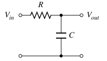 And here is a frequency-independent voltage divider: 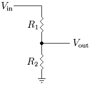 Notice that if you replace either of the caps in the filters with a resistor, the picture turns into a voltage divider. There are plenty of online calculators for filters, but I can't recommend one in particular because I don't use them. Maybe someone else can make a recommendation. When I have to figure out voltages that I can't get with pencil and paper, I use LTSpice to make a simulation. Once you start to understand how to read schematics, it becomes very easy to draw the schematic in LTSpice and find all the DC voltages. You can also look at waveforms in the time-domain (like a virtual audio-probe), and look at frequency responses at any point within the circuit. It's very useful and will teach a lot more about working with schematics. I'm not sure I understand the second part of your statement though (the part about calculating DC shift based on Vin, Vout, and C). Do you have a specific schematic or circuit snippet you are talking about? Remember caps block DC, so high and low pass filters will not necessarily generate DC shifts. A high-pass filter can have a DC shift from one side of the cap to the other, but the amount of shift depends on the other components and the circuit topology, not on the cap value. |
|
|
In reply to this post by motterpaul
I'm sorry, the moment you talked math and began to use formulas my eyes started to glaze over. Math was the one subject I consistently failed in my high school years. I have no problems doing basic accounting, but the moment you hit me with a formula my brain starts to shut down and time slows down to a standstill. |
|
|
Hell yeah - I here ya there! If I can get past the math, I suspect things would fall into place. As it is now, Im a decent "copier" but will probably never do anything above and beyond that. It appears I was "absent" from school the year I had Algebra 
Yeah, 220, 221. Whatever it takes.
|
|
|
In reply to this post by induction
"I'm not sure I understand the second part of your statement though (the part about calculating DC shift based on Vin, Vout, and C). Do you have a specific schematic or circuit snippet you are talking about? Remember caps block DC, so high and low pass filters will not necessarily generate DC shifts. A high-pass filter can have a DC shift from one side of the cap to the other, but the amount of shift depends on the other components and the circuit topology, not on the cap value."
The term "DC shift" came from your original post, and the word "shift" threw me at first, too, until I assumed it to mean a change in voltage before and after a cap. What I should have said is "a calculator to show changes in DC voltage based upon the Vin, the Vout OR the C value (two out of three) - not all three together. I think that makes sense, but if not, just forget I said it. As far as the math goes - it is not that hard once you have all the numbers to fill into the formula, which is just a matter of a few steps - and remembering Pemdas (the order is which you do calculations: parentheses, exponents, multiplication, division, addition, subtraction). I plan on getting into this thread more later but I just found out my band has a last minute "Cinco De Mayo" booking tonight so I have to bone up. Edit: I was a good student, but my forte was English & history. Math put me to sleep, but it isn't that hard, especially with today's calculators. It is just another thing where you paint by numbers - get the right numbers to fill in the formula parameters, and do the calculations in the right order. It seems to me the most successful pedal creators had to take this step, although after years of looking at circuits you start to instinctively understand what you are looking at - because you have seen it so many times before. But before you can look at a circuit and instinctively know what it is doing, you have to know what is happening with the voltage. I would like to see more schematics where the voltage of each node is identified. This is more common in tube circuits where you need different voltages (sometimes very high) to power different tubes. |
|
|
In reply to this post by induction
Question here:
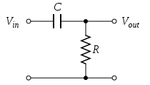 Here is a 1st order low-pass filter:  That is a beautifully simple thing - and this is what I was talking about when I said "developing a mental picture of how circuits work." Just by flipping the positions of the Cap and resistor you change a HPF to a LPF. |
|
|
I think what motivates us in electronics is application of the basic principles to the circuits of interest to us i.e. overdrives, tremolos, fuzz, reverb, delay...
To this end, I recommend the GGG article on how to design your own distortion pedal: http://www.generalguitargadgets.com/how-to-build-it/technical-help/articles/design-distortion/ As an aside, what I often find challenging about analyzing a given pedal design are: * understanding the effect of impedance on how gain/filter stages are designed * understanding the role of current on the operation of the circuit For example, we often see the voltage divider in induction's post in applications where we need 1/2 of the source voltage for biasing. To do this, we simply need R1 = R2, so that if the input voltage is 9V, the output is 4.5 V. Does it make a difference if we use 10K resistors versus 1M resistors? The output voltage will certainly be the same - BUT the ** current ** will be different according to Ohm's law (I = V/R). I often see a wide range of resistors used for this application, but have yet to fully understand how they arrive at their specific values. BTW - for this case, my experience shows that it should NOT make much difference what resistors you use if they are +/- %10 of the required value on the schematic. Since I'm always running out of 10K resistors, I've been substituting 11K resistors, which are much less often used. Works for me! 
|
|
|
That is a good article. (I had read it before, but it is good to review). The best thing is how it points out the similarities between different approaches, and also the unique requirements needed in different circuits.
By the way - I have never understood how diodes going to GROUND can cause clipping in the audio. It's obvious when they are in the feedback loop, or just in a loop coming off the audio chain, but I don't see how anything going to ground can change the waveform. |
|
|
"I have never understood how diodes going to GROUND can cause clipping in the audio."
Here's how I think of it. Imagine you have signal path downstream of an op amp gain stage. Your AC waveform (let's make it a sine wave for simplicity) has been pumped up to +/- 1V peak to peak by the op amp. All right! Gain!! But now it encounters a diode to ground. Let say it's just a single diode with its anode (+) on the signal path and the cathode (-) connected to ground. The diode is like a pressure relief valve in a fluid line (I'm a mechanical engineer so I like this analogy  ). As long as the signal voltage is below the forward voltage of the diode (let's say +0.7V), no current flows and it's like the diode is an open circuit (i.e. not there). Once the signal voltage tries to go above +0.7V, current starts to flow to ground and the voltage is prevented from going any higher (ideally) and hence stays near 0.7V. Therefore any part of your signal above 0.7V is clipped. Now, place another diode downstream of that and reverse the orientation (cathode connected to the signal path). In this case, all voltages below -0.7V are clipped. Hey, symmetric clipping! Of course, you can go hog wild at this point and use different diodes, diodes in series, etc to get different clipped waveforms. Note that the more the signal is clipped, the lower the amplitude of the signal will be, so you may need to add a gain stage to pump up the signal level again. ). As long as the signal voltage is below the forward voltage of the diode (let's say +0.7V), no current flows and it's like the diode is an open circuit (i.e. not there). Once the signal voltage tries to go above +0.7V, current starts to flow to ground and the voltage is prevented from going any higher (ideally) and hence stays near 0.7V. Therefore any part of your signal above 0.7V is clipped. Now, place another diode downstream of that and reverse the orientation (cathode connected to the signal path). In this case, all voltages below -0.7V are clipped. Hey, symmetric clipping! Of course, you can go hog wild at this point and use different diodes, diodes in series, etc to get different clipped waveforms. Note that the more the signal is clipped, the lower the amplitude of the signal will be, so you may need to add a gain stage to pump up the signal level again.
|
|
|
Thank you Frank - I never would have figured that out on my own. Good article, too, for describing all the functions of various caps in a circuit.
And thank you tremendously, Induction. Your knowledge is inspiring, and you helps to bring schematics down to a level where I can now visualize what is happening more than I could before. It is pretty funny when you realize most of any circuit is just plain resistors and capacitors, but that the way you use them makes all the difference. |
|
|
This post was updated on .
In reply to this post by induction
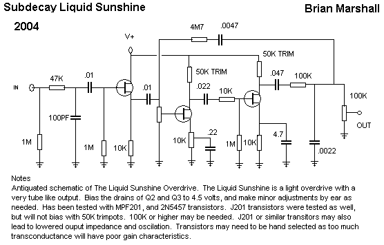
A note on LPF. I just built the Subdecay Liquid Sunshine which uses an odd "tone+drive" pot in addition to the regular gain pot. It seems to have a low pass filter, which I feel is voiced too low (I want more treble out of it). This combination drive/tone pot is 10k and it has lug 2 connected to a 220n cap going to ground.
 Now here is a low-pass filter calculator: http://sim.okawa-denshi.jp/en/CRtool.php I was reading Mark's layout guide where he discusses an LPF where he says: "The 1K resistor followed by the 150n cap to ground is a passive low pass filter to cut some high end after the gain stage. It starts attenuating at 1061hz, and so all frequencies below that are allowed to pass, frequencies higher are rolled off at 6dB per octave, meaning the signal amplitude is reduced by half every time the frequency doubles." Now, if you plug those parameters into the calculator above; 1kR and 150n -- you see cutoff frequency = 1061 - just as he says. If I plug in the parameters I see coming off the the Drive B pot (the tone pot) I get a cutoff freq of: 72.3 - this seems very low. Now, I know it is possible I am looking in the wrong place, but this is the tone control for this circuit. So, I am assuming this is a LPF because it is a resistor followed by a cap to ground. If I change that pot to a 1k - the cutoff freq goes up 10 times to 723 Hz which seems better. Or if I keep the 10k pot and change the 220n cap to 22n the cutoff freq also becomes 723 Hz. So, I tried that (it's easier), but I lost a fair amount of gain. So, on a lark, I tried soldering a 1k resistor between lugs 2 & 3 of the 10k pot, and WOW, what a beautiful change. This circuit now bleeds gain and tone. I will try to post sound samples soon. EDIT: that should say lugs 2 & 3, also I restored the 220n cap, so the frequency (rolloff) is about 723. The tone pot still works (rolls of highs) but it also has way more gain and clarity (midrange/treble) than before. |
|
|
This post was updated on .
The problem here is that the 10k pot/220n cap combination is not an LPF. It's a frequency-dependent gain control, not a passive tone control (notice that it's not actually in the signal path), so LPF calculations won't work here. This gain control has the same topology as the fuzz face gain control, and it allows you to set the DC bias independently of the AC gain. An important point is that, unlike an LPF, it boosts the gain of high frequencies more than low frequencies. The way it works is this: The voltage gain of a common source amplifier is given by Vg=-gm*Rd/(1+gm*Rs), where gm is the transconductance of the jfet, Rd is the source resistance, and Rd is the drain resistance. In this case, Rd is a trimmer, so its value depends on the setting, Rs is the 10k/220n combo, and gm depends on the jfet. Thus the DC voltage gain (biasing) depends on gm, the value of the 10k pot, and the drain trimmer setting (remember, for DC purposes, you can pretend the cap isn't even there). The AC voltage gain (amplification) depends on all of this plus setting of the gain pot (which determines how much the cap matters): Rs is actually equal to the resistance from lug 2 to lug 3 (Rr1) plus the parallel impedance of the resistance from lug 1 to lug 2 (Rr2) and the source bypass cap. Since gm and the trimmer setting are build-dependent (and to cater to those who don't do math), instead of calculating gains explicitly, we can just look at the operation in broad strokes. If gm is high enough (not a safe bet, by the way), we can reduce the AC voltage gain to Vg ~= Rd/Rs. At high gain settings, the source resistance is very low for high frequencies, which makes the gain high. Depending on cap value, the gain for low frequencies can be nearly as high (large cap) or much lower (small cap) because the capacitive reactance increases for lower frequencies, and this value is in the denominator. As you turn down the gain, the top of the gain pot starts to dominate over the bypass cap (ie. Rr1 becomes bigger) and thus the numerator gets bigger for all frequencies. At minimum gain setting, the cap is out of the circuit and the voltage gain is frequency-independent. So if you do the calculations (assuming gm=0.003 and trimmer set to 40k), you'll find this: Gain max: Vg(200 Hz) = 13.4 Vg(1 kHz) = 39.7 Vg(5 kHz) = 84.0 Gain middle: Vg(200 Hz) = 5.4 Vg(1 kHz) = 6.7 Vg(5 kHz) = 7.3 Gain min: Vg(200 Hz) = 3.9 Vg(1 kHz) = 3.9 Vg(5 kHz) = 3.9 So you can see that as you turn up the gain, the higher frequencies are boosted preferentially. If you increase/decrease the cap, the gain at lower frequencies will likewise increase/decrease. By adding the bridging resistor, what you've done is to rearrange the resistivity structure of Rs, which changes the gain response and makes the DC bias adjust with the gain knob. The result, assuming the same gm and trimmer settings as above, is: Gain max: Vg(200 Hz) = 13.4 Vg(1 kHz) = 39.7 Vg(5 kHz) = 84.0 Gain middle: Vg(200 Hz) = 12.2 Vg(1 kHz) = 22.2 Vg(5 kHz) = 30.6 Gain min: Vg(200 Hz) = 32.2 Vg(1 kHz) = 32.2 Vg(5 kHz) = 32.2 So what you've done is pretty clever. You've made it so that increasing the gain setting increases the gain for high frequencies, but decreases it for low frequencies. At maximum gain, yours is the same as stock, but at minimum gain you have close to 10x the gain as stock. According to my calculations, as you dial between 0 and 1 on the gain pot, the frequency-dependence kicks in, and the bass response decreases dramatically. I wonder if you see that in your circuit? Maybe I'll sim it if I can find the time. |
«
Return to Open Chat
|
1 view|%1 views
| Free forum by Nabble | Edit this page |