Hudson Electronic Broadcast

classic Classic list List threaded Threaded
73 messages Options
1234
Reply | Threaded
Open this post in threaded view
|

Re: Hudson Electronic Broadcast

Alex
That should be correct.
Not sure about the Gain pot orientation.
The same wire in the first picture seems to go to pin 1. In the second seems to go to pin 2.
I think the original transistor was an OC71.
Reply | Threaded
Open this post in threaded view
|

Re: Hudson Electronic Broadcast

rocket88
Administrator
Figured instead of postinghttps://hudsonelectronicsuk.com/bc-24v-ltd/ this on the main page, I think the 24V layout needs a little tweaking but I could be wrong. According to hudsons website the 24V limited edition has a 3 position gain switch and an internal trimmer go adjust the overall gain.

"Hand selected NOS Valvo black glass Germanium transistor
Specially chosen TRIAD Magnetics steel-core transformer
Alpha potentiometers
Neutrik jack sockets
Heavy duty footswitch (wired for true bypass)
3 position gain switch
Gain trim pot for the HIGH gain mode"

Only picture I could find of one of the 24V limited editions


Reply | Threaded
Open this post in threaded view
|

Re: Hudson Electronic Broadcast

Alex
Sorry Zach but I don't understand your message.
The one in your picture is the one we've reverse-engineered.
Could not find any gut shots of those with the 3 position gain switch.
Reply | Threaded
Open this post in threaded view
|

Re: Hudson Electronic Broadcast

rocket88
Administrator
something just doesn't make sense to me though. On their site all the 24v pedals say the switch is 3 positions not two and an internal trimmer for total amount of gain. Maybe I'm just missing something, my brain is fried still from finals.

The one that we're basing our trace on looks to me, could be wrong different then the one initially posted in the request. Not saying the layout is wrong, just that something is off from what Hudson says should be there. Besides, should be easy enough to figure out how to change the layout we have to make it fit the description on their site, no?
Reply | Threaded
Open this post in threaded view
|

Re: Hudson Electronic Broadcast

Alex
This post was updated on .
CONTENTS DELETED
The author has deleted this message.
Reply | Threaded
Open this post in threaded view
|

Re: Hudson Electronic Broadcast

tipunk777
Hello,
Rocket88 is alright my pedal is the "peach edition" and got a 3 position gain switch. However there is no internal gain trimmer in (they removed this information on their site...).
Reply | Threaded
Open this post in threaded view
|

Re: Hudson Electronic Broadcast

Alex
Thanks Tipunk.
I've deleted my last post.
Is it an SPDT On-Off-On switch then?
Reply | Threaded
Open this post in threaded view
|

Re: Hudson Electronic Broadcast

johnk
In reply to this post by Ciaran Haslett
Ciaran Haslett wrote
This more like it?  I'll post a hi res link when it's confirmed.

you have the OC75's emitter and collector reversed of what it should be. rotate it 180 degrees and it should work fine.
Reply | Threaded
Open this post in threaded view
|

Re: Hudson Electronic Broadcast

johnk
after etching and building one according to the schematic posted in this thread, and then comparing it to mine sonically, it's very, very close, but i prefer the sound of my original by just a little bit.

i modded mine to run on 18V internally a while ago and compared it to the new one running on 24V. the original on 18 volts can get perfectly clean, whereas there's a teensy weensy bit of distortion on the 24V one, even with the gain trim all the way down, so i took my original 9V Broadcast apart and traced it. (BTW, mine's the one with the high gain trim pot).

here's the schematic that i drew up for it and i intend to design & etch a PCB for it. hopefully, i will have it built up and ready for testing tonight.
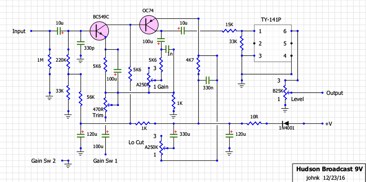
Reply | Threaded
Open this post in threaded view
|

Re: Hudson Electronic Broadcast

johnk
here's the original 9V version's layout. it's on veroboard only it has .133" hole spacing.

Reply | Threaded
Open this post in threaded view
|

Re: Hudson Electronic Broadcast

johnk
update. i etched a PCB and built the one with the high gain trimmer and i gotta say, to me, it sounds a lot better comparing them side by side than the one using the previous schematic in this thread.


Reply | Threaded
Open this post in threaded view
|

Re: Hudson Electronic Broadcast

johnk
In reply to this post by johnk
got mine done

Reply | Threaded
Open this post in threaded view
|

Re: Hudson Electronic Broadcast

johnk
gut shot:

Reply | Threaded
Open this post in threaded view
|

Re: Hudson Electronic Broadcast

Alex
Compared to Ciaran's schematic C3 & C9 values are different but the strange thing is that C3 & C6 polarities are reversed.
Reply | Threaded
Open this post in threaded view
|

Re: Hudson Electronic Broadcast

johnk
Alex wrote
Compared to Ciaran's schematic C3 & C9 values are different but the strange thing is that C3 & C6 polarities are reversed.
well, if you look at this layout, that's the way that it is on my original:

Reply | Threaded
Open this post in threaded view
|

Re: Hudson Electronic Broadcast

Addy Bart
In reply to this post by johnk
Beautiful, just beautiful
Reply | Threaded
Open this post in threaded view
|

Re: Hudson Electronic Broadcast

Alex
In reply to this post by johnk
I've seen the layout. From Teepunk's pictures they seem to be reversed and I was just wondering why they would reverse them on the 24V versions. Maybe we should reverse them too?
If someone that has built the circuit wants to give it a try...
Reply | Threaded
Open this post in threaded view
|

Re: Hudson Electronic Broadcast

Riku
This post was updated on .
I haven't seen any gut shot with a reversed C3. Not saying there wouldn't be one but just haven't seen. It's always the same way as in Ciaran's schem.

But, C6 is opposite direction on 9V models.

I build mine and added a switch for 9V / 24V and then tried to swap the C6 back on forth.. I hear no difference, nor do I 'feel' any difference.

Weird.

EDIT: Socketed the C6 and did some serious testing with the polarity with my giggin gear today (did use my small practice amp yesterday). Now I think I can tell the difference on the sound. Also did try with both the 9V and 24V.

With the polarity on the C6 as it is on Ciaran's schem (24V version); the sound is a bit clearer and cleaner, a bit less grit and maybe even a tad louder (?) than when it's reversed. This is audible running it at 9V or 24V.
Maybe they reversed the polarity of C6 on the 24V version to make it even more clean and clear sounding in addition to raised headroom and already added clarity of 24V?
Reply | Threaded
Open this post in threaded view
|

Re: Hudson Electronic Broadcast

brazdj
Good evening,

Raising a buried thread here, but hopefully an easy enough question.  Can I build the 9 volt version and then attach a separate 9v/18v charge pump as a daughterboard?  I mean other than making sure my components are adequately rated, does the 9v layout require any alterations to run on 18v?

I would use the 9v/18v charge pump Vero in the charge pump section on this site’s main library. Or if there is a better method, I would love to know!

Thank you in advance for your time,
Daniel
Reply | Threaded
Open this post in threaded view
|

Re: Hudson Electronic Broadcast

Vin69Nik
Hi all,

 I happen to have a Broadcast 24V, Peach Guitars limited Edition. I decided to trace it carefully, took pictures, measured voltages and drew a true to the original vero layout.

It might interest some of you as I noticed some differences in layout and pots' values.

Here are my findings:

vero layout, true to original

front view

gunshot with bottom plate

gutshot

main board top

main board bottom

power supply board top

power supply board bottom

potentiometers

gain switch

Voltages follow in a 2nd post.


Vincent
1234