Hudson Electronic Broadcast
1234


1234
|
The layout image is way too small to be readable...
|
|
I also noticed... I’m not at home now and will post a bigger image
or a pdf later |
Re: Hudson Electronic Broadcast
|
In reply to this post by Vin69Nik
Is there a higher resolution image of your layout available ? I built one of these recently but something seems off and I was interested in your effort. Thanks for sharing it
|
|
In reply to this post by Vin69Nik
Cool!
Thanks for your contribution! Will build this soon... |
|
In reply to this post by Vin69Nik
Vero layout as PDF
Hudson_Electronics_Brodcast_24V,_PG_Edition_vero_layout.pdf and the voltages:         All values are measured between ground (on DC jack) and desired pin. |
Re: Hudson Electronic Broadcast
|
Thanks man. This is great. We all appreciate the contribution.
|
|
Thank you for sharing! The pictures and the layout.
Can you or anyone clarify the PNP transistor used for Q2? Any suitable replacement, as I haven't been able to find any info on a 200789? Thank you. |
|
This post was updated on .
I´ve just built this last pdf layout using a bc550b for silicon transistor and for germanium, tried russians mp21a/gt108v. Both of them sounded nice with differences in texture and gain.
I just tried 9v power, but I´m planning making a voltage switch. I´m thinking on using 18v instead of 24, as some people stated in this forum, (and on tgp as well),that it worked better. I´m trying to understand the gain switch. I used a 3 positions on-off-on switch, so now I´ve basically have a medium/low/high gain switch. it seemed that the 470ohms resistor sets the gain for the medium gain position, because the high gain position just sends q2 emitter to the 68ohm resistor and straight to ground. So if we put a trimmer in place of the 470 resistor, we should be setting just the low gain mode, right? Anyway, so to my understanding, the only way of adding a second trimmer for the high gain mode using my layout would imply a more complicated switching network, right? And just out of curiosity. I seemed to understand that johnk´s schematics has not only a couple of caps with inverted polarity, but a different q1 emitter network that leads me to understand that that one could have even more gain than the layout I used. Anyone has experience with johnk´s schematics build? |
|
This post was updated on .
Finally I went for a bc549b and a mp21a.
Liked better powered with 18v. Peach guitars layout has some similarities with johnks layout. Shared C3 C6 and C9 cap values but C3/C6 polarity are inverted like in Ciaran schematics. Johnk's omited Q2 emiter 5.6k resistor to ground. Tried it on my build, but it went farty and it just didn't sound right, so back to where it was. Changing C3/C6 polarities is a matter of taste. I changed C6 polarity and left C3 alone. Placing a link where 68r resistor just gave a little more gain as I suspected. This is by far the most dinamic overdrive I've built with difference. Normally a good dinamic overdrive cleans up well, but always retain the pedal sound character. This one leaves your guitar tone intact when played soft and just breaks on a very beautiful vintage way with lots of harmonics when played hard. Delicious. |
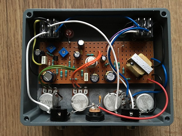
 This is one of the only images ive found of the inside of a dual. Peach layout too apparently. No cut side tho. |
|
I'd like to decrease that full range bass control.
What would be the bass cap here? Maybe the 330uf? |
|
In reply to this post by Vin69Nik
Apologies for the necro bump but I was wondering if someone can confirm the vero board pitch/spacing for this project? Is it standard 0.1inch or the slighty bigger (and harder to get!) 0.15 inch spacing? Looking forward to building this!
|
|
So reporting back after a few weeks of collecting components and self-isolation. I built Alex's layout, Vins Peach Guitars Layout and John's layout with the high gain trim pot. I used BC549C's for the sillicon transistors over all the layouts and a range of Germanium trannies for each. I did not make the 24/18v board yet to test so I can't comment on that but every single layout works perfectly. I have an issue with the peach guitars layout using and ON/OFF/ON switch in that both the on positions sound the same to my ears but nonetheless still sounds great. Alex's layout sounds as I believe the pedal should too with no problems there but my overall favourite has to be John's with the high gain trimmer, there's some beauty in being able to choose the maximum gain of the high gain channel! The only thing I altered was to add some extra cuts to allow me to solder the transformer to the board as I didn't like the idea of using zip ties. I used all the same capacitors for each layout, testing each capacitor to find the closest in spec one to each capacitor value required. Thanks to all of you for the contributions and I look forward to building more pedals from here. (maybe not another hudson broadcast for a while as I just have built 3 of them....)
Thanks! |
«
Return to Preamps
|
1 view|%1 views
| Free forum by Nabble | Edit this page |

