Insert Loop

12
12

|
This isn't a request for any specific pedal, but rather a mod for pt2399 delay pedals. Does anyone know how to add an insert loop to a pt2399 delay? The idea is to have only the repeats be altered by whatever effect you put in the loop. I'm trying to achieve whats going on at 6:00 into this video: https://www.youtube.com/watch?v=8xV7XDVkMzg
Thanks! |
|
|
In principle, this is very straightforward.
Most PT2399 delays feed the input signal to a buffer, then split the signal into a dry path and a wet path. The wet path goes through the delay circuitry (including a feedback path for repeats) before being mixed with the dry signal at an output mixer stage. If you want the insert effect to color the wet path only once, you can place the insert loop in the wet path, either just after the input buffer/splitter or just before the output mixer. If you want the insert effect to color the wet signal more for each repeat (like in your link), you can put the insert loop between the delay output and the repeats control. You may want to buffer the insert send and/or return so it will behave predictably with different insert circuits. For more implementation details, you'll have to commit to a specific delay circuit. Many of them are pretty similar, but they can vary enough to make a difference in the particulars. |
|
|
Thanks for the reply!
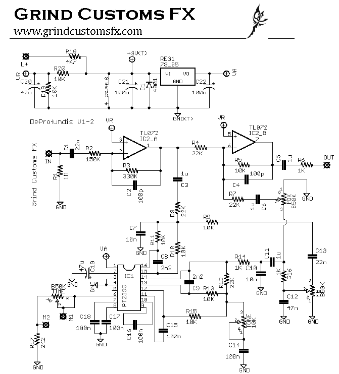
I've built the Grind Customs FX DeProfundis delay so I'll use that as an example. Could I disconnect a wire from one the repeats pot lugs and then wire a send and return jack back to the lug I disconnected? I need to learn more about the pt2399 and reading datasheets in general so I know more about which pins are serving which functions. How do I know which pin is controlling the delay time or delay feedback? Or is it a combination of pins? I'm sorry if my questions are confusing or if I am too much of a beginner for this stuff. I really appreciate your help and I've already learned a lot from this reply and your replies from my other questions. Thanks again! |
|
|
Here is the link for the DeProfundis: http://tagboardeffects.blogspot.com/2014/04/grind-customs-fx-deprofundis-delay.html
|
|
|
In reply to this post by jghfslk
Here is a particularly useful datasheet for the PT2399. The block diagram shows the internal connections of the chip. I'll let you explore the details on your own, but in broad, massively oversimplified strokes, the input is fed to pin 16 (LPF1-in), then converted to digital, converted back to analog again, and output from the chip via pin 12 (OPF2-out). This output is often fed into pin 13 (LPF2-in) for additional filtering and comes back out via pin 14 (LPF2-out). The digital conversion and intermediate RAM storage of the signal is what creates the delay. To get both the dry signal and the delay, the output of pins 12 and 14 are mixed with the buffered input signal. (The output of the chip is delayed signal only, the dry signal is not present.) The amount of delay is controlled by the resistance between pin 6 (VCO) and ground. The delay control is generally a variable resistor: increase resistance for more delay. If you look at the block diagram, you can see that many of the pins connect to the feedback loops of internal op-amps, and are used for filtering the highs out of the delayed signal. (Digital conversion leads to high frequency noise, which you want to get rid of.) Many of the components surrounding these pins are chosen to tune the filters. The chip only creates one delayed signal, so if you want repeats, you have to split the chip output and feed one of the paths to the output mixer, while feeding the other path back into the chip input, which adds another delay. The Repeat/Feedback control is just a volume pot (voltage divider) on the feedback signal. If the amount of signal fed back into the input is weaker than the original input signal, the repeats will decay away like normal echoes. The louder the feedback signal, the more repeats you'll get. If the feedback signal is louder than the original signal, the repeats will get louder and louder until it oscillates. If the feedback signal and the original input are precisely the same volume, you will get infinite, steady (but heavily filtered and degraded) repeats. For the rest of this post to make sense, comparing the schematic to the layout will be very useful. That would work for most of the repeats, but the very first repeat will never see the insert loop. (Recall the output pins mentioned above, and stare at the schematic until you can see why this is true. Let me know if you need a hint.) If you want the first repeat to go through the insert loop, it would be better to put the insert between R14 and C11 (after C10, not before because R14 and C10 together form a low-pass filter and putting the insert loop between them will screw up the filter frequency). Like I said before, you may want to buffer both sides of the insert loop, but you should try it on the breadboard first, to see if that helps or hurts. Try it with several different insert effects, because they may not all behave the same. No apology necessary. I'm glad to help, and your questions make perfect sense. Asking questions is how beginners become experts. Keep exploring and soon enough it will be your turn to help out a beginner. |
|
|
Thanks again for the help!
It helps to have a more in depth explanation of the chip, even if overly simplified (still complex enough for my brain) Unfortunately I couldn't find the schematic for the DeProfundis. The link did not work and I tried to find it from the publisher's website (where I originally found it) and it appears that they took it down. My guess to as why inserting the loop from the repeats pot wouldn't affect the first repeat is because the chip only creates one repeat and the signal has not been fed back into the chip again? |
|
|
The link still works, but the pdf is hosted on dropbox, which is often blocked as a security risk on larger networks (like the one at my job). Anyway:
 I'm not sure how familiar you are with schematics, but now that you're asking design questions you can't really get where you want to go with layouts only (well maybe you can, I don't know, but I certainly can't.) |
|
|
It definitely helps to have the schematic. I like to compare the schematic to the layout to try and figure out what is going on. I'm still trying to wrap my head around why the first repeat won't see the loop. I think I actually want the first repeat to not be altered by the loop but I would still like to know the reason for it. Does it matter which lug of the repeats pot I would put the insert into?
|
|
|
Trace the signal path on the schematic from input to output. If you can't do it on the screen, print it out and use a pencil. In through the input cap and through the first op-amp (IC2_A), after which it splits into two paths. To the right is the dry path (R4) which feeds directly into the output mixer (IC2_B). The downward path is the delay sidechain. It goes through C3, etc. into the input (pin 16) of the PT2399. The signal goes through the chip and out (now delayed) from pins 12 and 14, where these two signals are mixed together at the junction of R12 and R14. On the right side of C11, it splits into two paths. The first is the output path, which goes upward, through the mix pot and into the output mixer. The second is the feedback path, which goes down through R16, through the feedback pot, and gets sent back into the PT2399 via pin 16. That split is the answer to your question. The output path doesn't go through the feedback pot, so if you put the insert loop on the feedback pot, the first repeat will never see it. The insert effect will only process the feedback path. However, there may be some bleedthrough of the effected signal because the feedback signal has a path through R8 and C3 back to the dry path. Thus you might hear some of the insert effect on the first repeat in addition to the uneffected signal from the delay output path. The strength of the bleedthrough signal will depend on the feedback pot setting, but not the mix pot setting. It's very hard for me to guess how audible this bleedthrough signal will be without trying it on the breadboard, and it will depend very much on the particular insert effect. If the insert effect is a pitch shifter, and the bleedthrough is audible, you will get harmony repeats. The first will be the original pitch combined with one shift. The second will be one shift combined with two. Might be cool, might not. Certainly won't be diatonic, but neither will be the pitch shifts without the harmony. You'll just have to try it (on the breadboard, I would suggest) and see how it works and if you like it. Let us know what you find. How much it matters will depend on whether you buffer the insert loop, and what circuit is in the loop. Either way, you'll get more consistent results if you feed the insert loop into lug 2 of the feedback pot. That way, the source impedance of the feedback signal is consistently affected by the feedback pot. This may help reduce bleedthrough (which you may or may not want), but again, very hard to predict without breadboarding it. Bottom line: if you want to optimize the modded circuit, you should spend a lot of time on the breadboard, trying different approaches to see what works best for you with all of the different insert effects you think you'll ever use. If you just want to do it once and get it over with, put the insert loop in front of lug 2 of the feedback pot and call it a day. Hope this wasn't too confusing. |
|
|
Very helpful reply once again! I was thinking it had something to do with the loop being before the mix pot, but it makes much more sense with you explaining it.
I had a working cave dweller delay that I made a while back so I tried disconnecting lug 2 of the "dwell" pot and inserting a loop there. It was cool and was affecting the delayed signal but there was a lot of noise. When I grounded the jacks I was using for the insert the delay went away. I took the wire from the dwell pot and wired it to a 1/4" jack. I wired another jack back to the dwell pot and inserted a pitch shifter between them. When I connected the ground lug of the jacks to ground I lost my delay signal. Am I missing something obvious here? The effect works when the jacks aren't grounded, but not when they are. Here is the cave dweller schematic: http://www.luciferstrip.com/fuzz/cavedweller-schematic.jpg |
|
|
The Cave Dweller is not a good platform for what you're trying to do. Unlike most other PT2399 circuits, it does not have a dedicated dry path that is mixed with a dedicated wet path. Instead, the dry/wet mixing is done directly on the chip. The feedback pot doesn't work the same way as it does on most other PT2399 circuits. |
|
|
I didn't think the cave dweller would work the way I want the DeProfundis to work, but should this loss of signal when grounded happen? I'm more concerned that I'm doing something wrong with the insert loop and the same thing will happen when I try it with the DeProfundis.
|
|
|
No, it shouldn't kill all repeats to try the insert loop there, even if you accidentally ground lug 2 of the Dwell pot. It's hard to say exactly what went wrong without the unit in front of me, or at least pictures, but I think you probably didn't do exactly what you thought you did.
In any case, the Cave Dweller V1 and the de Profundis are very different topologies. You shouldn't expect anything you do to one of them to carry over to the other. |
|
|
I tried inserting the loop in a DeProfundis and it worked! I want to try to have the loop affect the repeats only once for each repeat (If there were an octave up pitch shifter the first repeat would be up one octave, second repeat 1 octave, 3rd=1 octave, etc.) Am I correct in thinking that the insert loop should go somewhere after c11 so that it doesn't hit the feedback pot, and it should also go before c5 so that my dry signal does not get affected by the pitch shifter?
|
|
|
Just to clarify, you want the dry signal to be unaffected by the pitch shifter, and all of the repeats are shifted a total of once? So original note is E2, first repeat is E3, second repeat is E3, third repeat is E3, etc.? If this is correct, then you can put the insert loop somewhere near C3 (anywhere between the junction of R4, C3 and pin 1 of the TL072, to the junction of R8, R9, R10, R11 and C7). The pitch shift is done once before the signal gets to the delay circuit, and the feedback path doesn't see the pitch shifter again.
On the other hand, if you want each repeat to be pitch shifted once for each additional repeat (original note is E2, first repeat is E3, second repeat is E4, third repeat is E5, etc.), then you probably want to put the insert loop in front of lug 3 of the the Mix knob. |
|
|
I think I'm getting confused on some of the splits for this circuit. You were correct in understanding what I am trying to accomplish (original is E2, 1st repeat E3, 2nd repeat E3, 3rd repeat E3, etc.) If I put the loop on lug 1 or 2 of the mix pot, would that signal go back to the feedback pot and then fed back into the pt2399? The signal splits at c11 and goes to the mix pot and also the feedback pot. Is the signal that goes to the feedback pot being affected by the loop even though the loop would be inserted at the other part of the split? (split after c11) I was thinking that if I put the loop by the mix knob the feedback pot wouldn't see the loop, so every repeat that got sent back into the pt2399 would be unaffected by whatever effect is in there until it goes to the mix pot.
|
|
|
You're right, I screwed that up. Good catch.
Either of the ways I described in my last post will give you what you want: A single pitch shift for all repeats. You can either shift the pitch before the signal reaches the delay circuit (specifically before the path reaches the feedback return, so near C3 or R8), or after all of the repeating has been done (Mix pot lugs 2 or 3). The two options may sound slightly different, but near the mix pot is easier if you want to use the layout without modifying it. If you wanted an extra pitch shift for each repeat, you could again do it at the input of the delay circuit, but after the feedback return (before R11, for example), or after the delay circuit before the output/feedback split (before or just after C11). Sorry about that. |
|
|
No worries :)
I am testing a DeProfundis with a loop in it now. I am trying it so I can have 2 possibilities for loops. I drilled holes in an enclosure for a loop send and return. I also drilled two holes for 2 spst switches. For one loop I took the wire that normally goes to lug 2 of the feedback pot and connected it to the center of one of the spst switches. One side of the spst goes to the feedback pot and the other goes to the input jack of the loop insert. For the other loop I took the wire that normally goes to lug 3 of the mix pot and connected it to the center terminal of the other spst switch. One side of the spst switch goes to the mix pot and the other goes to the send of the insert loop. The jack that is being used as my loop return is connected the 2nd lug of the feedback pot and the 3rd lug of the mix pot. When both spst switches are off and the jacks are not grounded, the delay acts as normal. When both spst switches are set to bypass the loop and the jacks are grounded, I don't get nearly as many repeats. Even all pots turned all the way up, I only get 3 or 4 repeats. When the spst switch that is connected to the mix pot is set to go through the loop, the delay acts as normal. When the spst switch that is connected to the feedback pot is set to go through the loop, I will get more repeats than when the spst is set to bypass, but not as many as normal (the delay won't self oscillate). This is all happening when the loop jacks are grounded. Do you have any idea what is causing this? I know this is a lot to try to comprehend without any pictures, but unfortunately I don't have a camera at the moment. |
|
|
Hello, I am sorry to interrupt your thread, but I have a related question that hopefully could be answered quickly in a single reply, so, if it is ok...
I am hoping to do exactly the same but with a clone of a DBA Echo Dream 2. Am I correct in thinking that on the schematic below I would have the loop send and return to the left of the feedback pot, after the 1u capacitor but before the split sending the signal into the feedback loop and to the output mixer? That is what I had worked out myself from following the circuit, and I think it is consistent with what you have said for the DeProfundis circuit. 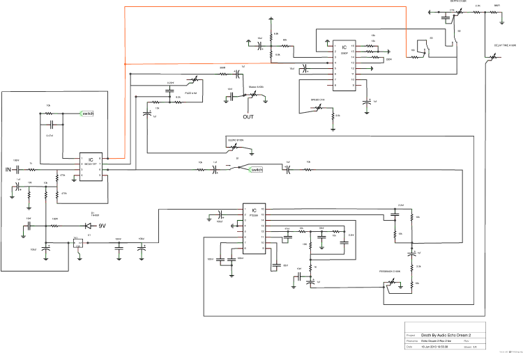 I had not thought of buffering the input and output of the loop, I can see why that would be useful, thank you. I apologise again for the interruption, but the topic was so close to what I had been wondering about myself that it seemed a good opportunity. (Edited to try to resize schematic image. Not great success. Sorry). |
|
|
In reply to this post by jghfslk
SPST switches only have two lugs, so I'm going to assume (unless you correct me) that you used SPDT switches. This is going to cause unexpected results and the conclusions we came to previously about which repeats will be affected by the insert loop will no longer apply. No matter which loop you choose, you will send the insert loop to both the output (via the mix pot) and the feedback loop (via the feedback pot), so the insert loop will process the signal an additional time for each repeat. The only thing that changes depending on the switch positions (unless I'm misunderstanding your description) is whether you are also mixing dry signal with the effected signal on either the mix pot or the feedback pot. I'm not sure what you mean by 'the switches are off'. Normal SPDT switches have two settings: in this case you can either engage the insert loop or bypass the insert loop. Some SPDT switches have a center-off position where no connection is made to either outer lug. Do your switches have two settings or three? Do you have anything plugged into the insert loop when you do these tests? Also, you have mentioned problems when grounding the jacks a few times. Are you referring to grounding the tip connector or the sleeve connector of the jacks? How many lugs do your jacks have? Grounding the sleeve connector on the jacks will have different results depending on several factors, so a picture or diagram would really help here. Likely, the results you are getting are related to the multiple signals being mixed together in unclear ways, so there isn't much more I can say without more precise information. |
«
Return to Requests
|
1 view|%1 views
| Free forum by Nabble | Edit this page |