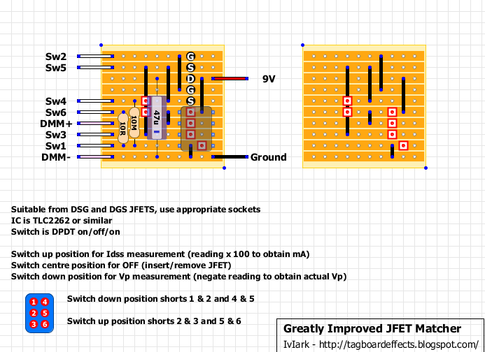
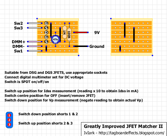
Jfet tester
|
I have built every single Jfet tester on this site. Now - I realize I made some mistakes on some, because sometimes it is the "simple" circuits that throw you a curve ball. For example - I didn't expect DPDT switches to be numbered like
1 4 2 5 3 6 when ICs are numbered like 1 8 1 7 3 5 4 5 So, I wired my switch incorrectly (at first) and did not notice it. But anyway - with all the FET testers I have built, I don't seem to get consistent results. Sometimes I will plug in a J201 and I get one set of results - then I turn off the tester and start over, and I get completely different results. Here is the last one I built (I used a TL082):  When I plug in a J201 with switch in center, it reads 7.92 v When I switch it up to read IDss I get 1.29v When I switch it down I get .129 A different J201 center reads: 7.72 Up reads 1.20 Down reads .119 Down is supposed to be Vp, and I see you are supposed to make it a negative number to get true results. Does this look right? Also - does anyone have a simple mod to make the center position truly off? Finally, if anyone is using a different tester and finds it worthwhile - which one is it? (to be clear about "vastly different results" - sometimes I will use this same tester and a tranny will read 000 - unless I start over and then it is OK.) I tried the one below, but it did not seem to be consistent, plus once again, center was not off (though I see the schematic has a simple toggle switch)  |
|
This post was updated on .
Different FETs will have different parameters, that's the whole reason these circuits exist. I have not tried the op-amp based tester, but the two-resistors one works well enough for me that there's no reason for the extra complexity. Your numbers look alright, I can give you an example from my tester: a 2N5952 that reads Vp=3.233 and Idss=1.028. Numbers can be highly, highly variable. Check out the RoG Fetzer Valve page for some examples, they use the simple tester you've shown below and I've found their example numbers to be accurate.
As far as your "off" question, yes there is. I've actually made a combination tester that tests n-channel JFETs and NPN and PNP germanium transistors that incorporates this. Here's the thread, where you can find a schematic. Basically you use a DPDT On/Off/On switch and run 9v to the up- and down-poles of one half of the switch so you switch the power along with the mode, and it's all off in the center. Also I think you mean 1 8 2 7 3 6 4 5 for the ICs. 
Through all the worry and pain we move on
|
|
Administrator
|
In reply to this post by motterpaul
The IC pin designation was decided by the manufacturers a long time ago and they have all stuck to the same numbering since which is why we show it in a way that conforms to their datasheets.
There is no such standard with switches and so they are numbered the way logic would best dictate, 1 to 3 for the first pole, 4 to 6 for the second pole and 7 to 9 for the third. |
|
And I appreciate the fact that you DO show the pinouts on the various switches - otherwise I would assume they worked in different ways (or are numbered differently, at the very least).
The more I do this the more I realize how much there is to know (switch numbering is a good example) I spent most of the day reading up on FETs. I compared schematics to the layouts and that is yet another thing to know - that in a schematic FET connections are in a different order than in the real world (for most FETs). Mostly, I just want to be able to tell if my FETs are good so I can rule them out when something I have does not work. I would like to be able to tell a "strong" J201 from a weak one. Silver - you tester is very impressive. I already have HFE on my DMM. I tried the "simple" FET tester from GeoFex and for some reason I kept getting inconsistent results, but I guess the one I have now is finally working well enough |
|
Haha thanks. Yeah obviously you don't need to incorporate everything if you don't need it, but an hFE meter isn't useful for JFETs or germanium BJTs so if you regularly use either I think it's a good all-in-one solution (if you're prepared for a little finagling lol).
Through all the worry and pain we move on
|
|
In reply to this post by motterpaul
"Mostly, I just want to be able to tell if my FETs are good so I can rule them out when something I have does not work. I would like to be able to tell a "strong" J201 from a weak one."
Measuring JFETs is the way to go to determine if they'll work in a given circuit. I wrote my JFET spreadsheet to answer this very question for the ubiquitous common source JFET gain stage, especially for some of the Wampler designs which don't have drain trimmers. From my experience with J201s, those can vary quite a bit in Idss and Vp. My J202s and 2N5457s are more uniform, but still have some variation. |
«
Return to Open Chat
|
1 view|%1 views
| Free forum by Nabble | Edit this page |

