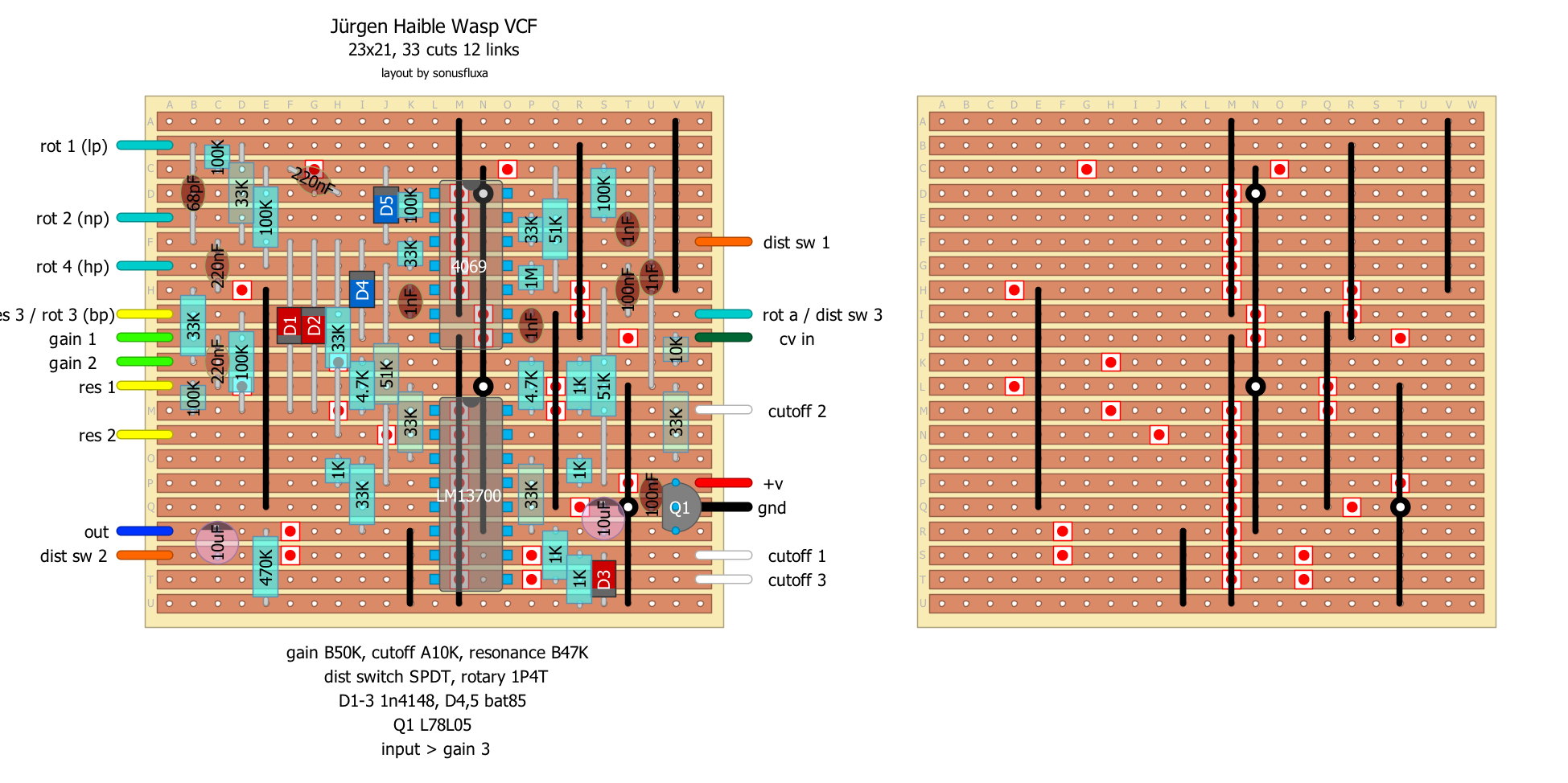
Jürgen Haible Wasp VCFilter
|
Built this up last night and it seems to be working as expected. Only got to mess around with it for a short amount of time. I'm gonna have to order Bat85's but for now I'm testing out different diodes.
|
|
In reply to this post by SonusFluxa
I built it and it sounds good. I would use a B10K for the cutoff and I reversed the 1 and 3 for the resonance. I am building it with the cv input and with an expression jack for the cutoff.
|
|
In reply to this post by SonusFluxa
many thanks for the great layout, sonus. how does it sound to you? nasty-bad in a good way?
have never heard of bat85 diodes. i wonder what's so special about them that a 4148 or similar won't do the same job? will order some anyway as this is a must-build. is one of these chips available in a buffered and unbuffered form (denoted by the suffix)? i'm sure i read somehwere (though can't find it for searching now) that this vcf self-oscillated better with the unbuffered ic. if you have both and you have built this it might be worth trying both for the sake of comparison. i will search again later tonight, but i remember reading it somehwere and making a mental note about the unbuffered thing. great work sonus! |
|
In reply to this post by SonusFluxa
Can anyone tell me what the cv in is for. Thanks
"Red velvet lines the black box"
|
|
Hozy - Since this is originally a synth effect, this allows control voltage from an LFO/sequencer/what have you to modulate the filter in an automated fashion, or sync it to a tempo you have running. If using in a guitar context, I imagine you'd similarly attach an LFO and use it as an auto-filter.
Tabby - I've only had a brief chance to play around with this along with my other synthy bits (been working on getting some panels/a case prepared), but with the distortion on, definitely getting some nasty acid sounds, which I think will open up further when I get a chance to test out different LFOs. The BAT85 is a Schottky, so in its place I'm using a 5817, which I've read elsewhere isn't a perfect substitute, but will have to do until my eBay order arrives. On the schematic it mentions their use as CMOS protection, so not sure their contribution to the overall sound. Might try some others I have in the bins in the meantime, see if it makes a difference. Re: 4069UB, an explanation that might make sense from Logic Noise. Unbuffered allows for use with digital or analog signals, as far as i can tell, which is what we're after here for use with guitar or bleep bloop click clack robot fart machines. |
|
Thanks Sonus. Just built it up with BAT85s and must say what a great filter. Cheers for the layout. I used yours as it should squeeze into a 125B perfectly.
"Red velvet lines the black box"
|
|
This post was updated on .
In reply to this post by SonusFluxa
thanks for your thoughts and comments re the wasp and 4069. have just looked at the only 4069 i have and it's 4069BE (buffered) so will order another to do the wasp properly and make your modlunetta in the meantime. i've got a 4046BE, or does that have to be unbuffered too? layout doesn't specify. while distortion is desirable in the wasp maybe less so in a vco? thanks for posting the modlunetta vco. may be worth dragging that out of the cmos melody generator thread and giving it its own dedicated thread. it's a nice little core element and a neat layout. am already thinking about how the saw can be modded to saw/reverse saw wave. and there seems to be lots that can be done with pulse waves. aren't synths great compared to playing guitar? you don't even have to move your arm. just sit there like a cabbage and make the ic's do all the work. the future has arrived. |
|
In reply to this post by SonusFluxa
btw, if you like wave porn i can highly recommend 'the twelve days of modular' series. it's really interesting to tune into the characteristics and idiosyncrasies of all the different waves and really get a feel for what they can do. have watched this series about a million times. sometimes i have the series on autoplay as background music and play 'guess the wave'. i'm on the spectrum like that.
|
Re: Jürgen Haible Wasp VCFilter
|
In reply to this post by SonusFluxa
Would anyone be interested in producing a stripboard layout of this?
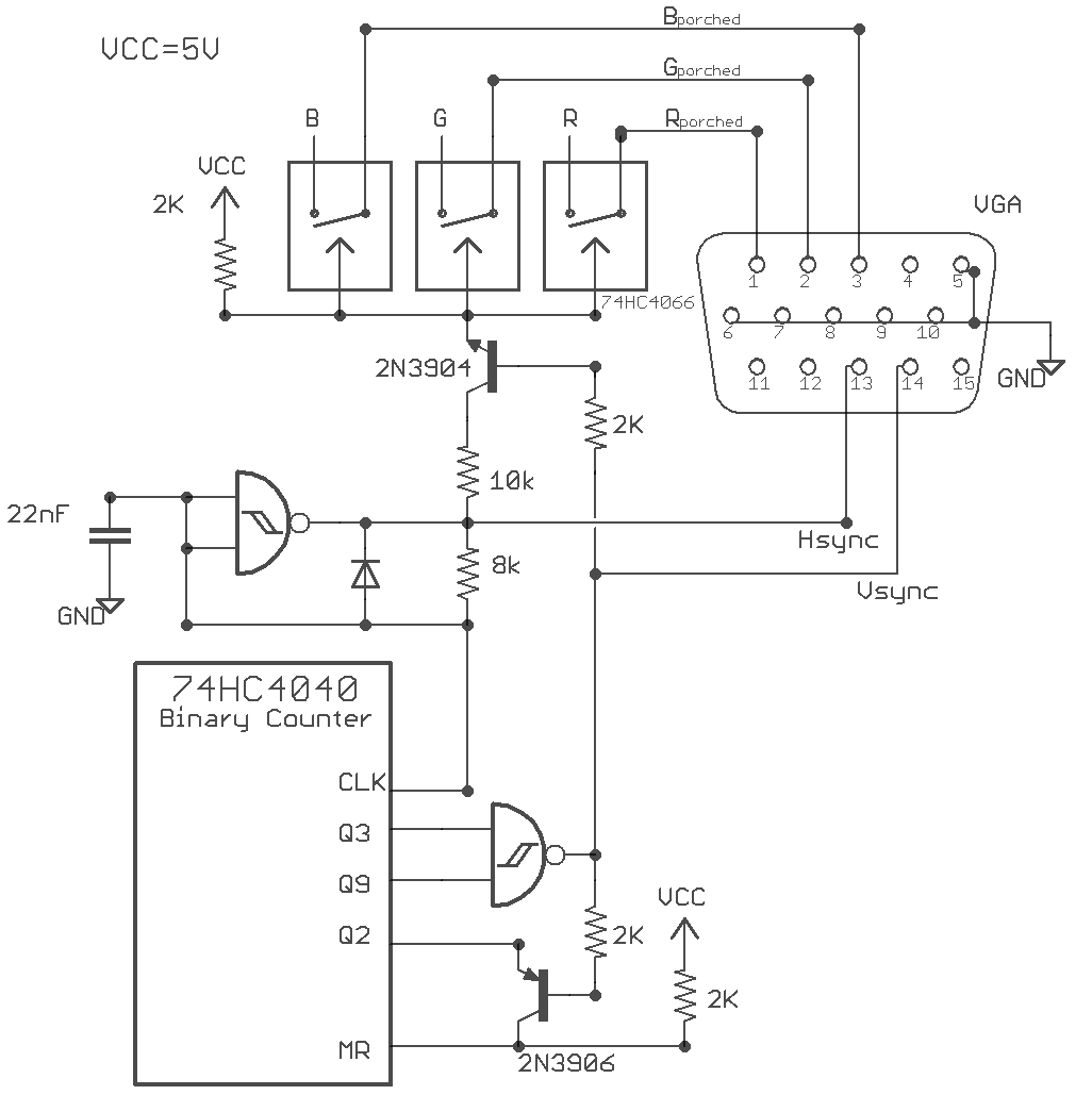
 It is from this Hackaday project:https://hackaday.io/project/9782-nes-zapper-video-synth-theremin/log/32282-vga-porching It's for producing a VGA synch signal from discrete logic. So it could add video capabilities to your CMOS synths! |
|
Hozy - Glad you're enjoying the filter!
Tabby - Gave the VCO its own thread. I've got a few other synth layouts that I think should be set to go, but haven't tested them yet. Might just post them anyway. Thanks for sharing the youtube series, definitely gonna check that out when I have a solid block of time. I'd be interested to know if the buffered/unbuffered makes a difference in the different circuits, and what impact it has. Pretty much spent all of my building time on synths (layouts and building), once I have my case built and a few modules in it, I'll post some pics in the pedal guts (synth guts?) thread. Skeletonghost - HOLY SHIT. This is something that I'm going to be looking into very seriously in the coming weeks. I've been very interested in video synthesis since I saw an old vid synth in the production studio at my school when I was in college. The thought that we can bang one out with CMOS is insanely exciting. My thoughts on this project: syncing the video to various audio sources, not just the built in chips, and finding another way to control it other than the light gun. Thank you a ton for sharing this. Maybe give this its own request thread so we can get other people in on it? |
Re: Jürgen Haible Wasp VCFilter
|
Sonus - It is the simplest implementation of VGA sync that I have seen using discrete logic. In the past I have used arduino (you can also find cheap VGA sync boards from aliexpress) but I like this solution better, as it doesn't introduce and microcontroller into the mix.
You can already control it without the light gun! The "sync" refers to timing signals that are generated to center the image in the frame. A VGA signal requires a H-sync and V-sync (horizontal/vertical) signals (timed to a specific frequency) to display properly. The RGB in the schematic have inputs where one could feed signals (like audio/guitar/cv) to create images. The quad switch is used to "porch" the RGB signals so they are only on during a specific period to display properly. I'll make a request thread! |
|
In reply to this post by SonusFluxa
Hi,
Thank you very much for the layout. I had found another one earlier this week, which seems easy to built, but lacks some protection diodes, and is more Eurorack orientated", as all the filter outputs are featured on separate jack sockets. You can find the layout here: https://billsabandija.blogspot.com/ Your design seems a bit more comprehensive (it features the BAT85), and everything is laid on the veroboard, which is nice. I would have a couple questions, however : 1- what is "NP" ? Does this mean "Notch filter" ? 2- I don't have a 1P4T rotary switch, could i use a "regular" SP3T instead ? 3- Instead of a switch, would it be possible wire each filter output to a potentiometer (and mix freely each filter's output to a single mono main output), or would it cause volume and impedance issue ? 4- Would anyone know how to make the "self-oscillating resonance mod" which is described here ? The mod description applies to the Doepfer module, so i don't know how to spot the correct resistor... http://patchpierre.blogspot.com/2011/05/filters-iii-124-wasp-filter.html http://www.doepfer.de/DIY/a100_diy.htm 5- Did anyone try the "FM mod" described here ? From my (very little) understanding of schematics, it involves using another chip, but it seems to be a rather simple circuit to build on a daughter board... http://www.modular.fonik.de/Page38.html http://www.modular.fonik.de/pix/F_wasp_1.jpg Thank you all in advance :) |
«
Return to Synths & Noisemakers
|
1 view|%1 views
| Free forum by Nabble | Edit this page |


