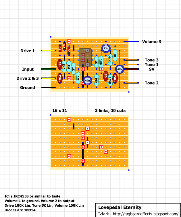
Lovepedal Eternity Problem
12

12
|
Hey all!
I built an eternity board this afternoon based on the attached version. When I power it up, it makes a crazy oscillating sound that goes up in pitch until it farts out to total silence. Whenever I try to play through it, it makes extremely farty gate sounds. I can hear the chord somewhere in there, but it only lasts for a split second. It's like it's a fart pedal with an extreme gate on it. Lot's of fart. I went to the Lovepedal tag and looked up the eternity, and saw that the one currently up has the 47u electrolytic up toward the top of the board with an additional cut and double link. I did all that, and when I power it up it does a longer oscillation thing before farting out. OH YEAH I didn't have a 5k for tone so I used a 10k but didn't think that would make a huge diff. Let me know if I'm way off here and this is the source of my woes. could only source a 56n cap, no 55 also. Everything else should be exactly as the board. I checked for bridges, found none. I swapped out my 4558, same thing. Any idea what could be causing this? Thanks y'all. 
|
|
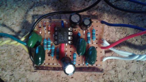
Measure your IC voltages and report them here. Also take some pics and post them. Thanks!
|
|
thank YOU!
1: 7.78 2: 7.71 3: 7.17 4: 0 5: 7.78 6: 7.78 7: 7.78 8: 8.36 let me know if there's a better angle I can take, etc. Where do you find what voltages the pins should be at? I'm going to reinspect but I'm pretty sure I have this right. there's an extra strip at the bottom that I sharpied, I didn't feel like cutting it.  |
|
just caught that the 47u at the top's positive lead wasn't in the right hole coming off of pin 8. I fixed that, still have the same problem.
|
|
Your IC voltages are not right...should be closer to 4.5 V. THis likely the source of your problem .Check the two 10K resistors to the right of the IC. Is one of them 1K rather than 10K?
|
|
I am completely stumped. I checked and measured the values of the resistors to the right of the IC, and they're right. Just so I understand, the 390 and 10k resistor are supposed to pull the voltage down to the right level, correct? very confused, any idea on what I should do to further check it?
|
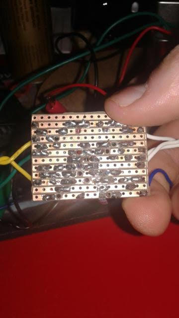
The bias voltage divider is the two 10k's to the right of the IC. The lower one should have ground on the lower leg and 4.5 V on the upper leg. The upper 10k should have 4.5 V on the lower leg and 9 V on the upper leg. Can you measure these points for us? Also a picture of the copper side of the board would be helpful. |
|
Like induction said, you should be getting around 4.5V at the junction of the two 10K resistors (which form a voltage divider). The fact that all of your IC voltages were too high indicates a problem there. I couldn't see the value of the upper resistor from your image, and thought it might be a 1K rather than a 10K. If it's OK then check for a solder bridge.
|
|
OK, the upper leg of the furthest right 10k resistor is 7.85 (this is the one on the same row as pin 8 of the IC), and the other side of it is also 7.85. I switched my ohmmeter to 20K and measured the resistor, and it read just below 10k, so I am really scratching my head here.
The 10k resistor that shares the same strip as the lower leg of the first one is at 7.83. On the lower leg which connects to ground, it is 7.82. I measured this one also and it was right below 10kohms. I know it's going to be sweet when the code is cracked, but this has me really baffled. I am new to it of course, so even when these go perfectly, it can still be confusing. I included a clearer picture as well as a pic of the copper side. I went through and checked again for bridges, but found none. If it were due to a bridge, where would I want to check again?  
|
|
The bottom row where you measured 7.82 V is supposed to be ground. If your measurement is accurate, then you have a bad ground connection somewhere on that row. Remelt all those solder joints and try again.
|
|
Fyi, I was actually measuring the leg of the resistor on the top side. But I can't imagine why that would make a difference. When I measured the actual track, it was 0. But I will give it a shot tonight. Thanks again for all the assistance.
|
|
If the track measures 0 V, but the resistor leg measures higher, then that resistor has a bad solder joint on that leg. Remelt that joint and any others that look dodgy.
|
|
Awesome, Thanks!!! Sent from my T-Mobile 4G LTE Device -------- Original message -------- From: "induction [via Guitar FX Layouts]" <[hidden email]> Date:11/25/2015 8:29 AM (GMT-06:00) To: ham_phist <[hidden email]> Cc: Subject: Re: Lovepedal Eternity Problem If the track measures 0 V, but the resistor leg measures higher, then that resistor has a bad solder joint on that leg. Remelt that joint and any others that look dodgy. If you reply to this email, your message will be added to the discussion below:
http://guitar-fx-layouts.42897.x6.nabble.com/Lovepedal-Eternity-Problem-tp26192p26272.html
|
|
I refuse to quit on this thing. I re-flowed the solder on the ground and that was the problem! However, now I just have noise and no signal coming through. The noise seems to behave as it should when I turn the tone pot and volume. Just no signal coming through.
1: 3.66 2: 3.66 3: 3.34 4: 0 5: 3.25 6: 3.26 7: 4.07 8: 7.29 I am guessing Pin 8 should be seeing 4.5ish volts, right? I guess I don't really understand the properties of how electricity works, but wouldn't pin 8 need to be where the junction of the two 10k resistors are? That is where the voltage appears to be correct. Instead, it's on the top leg of the first 10K resistor, which is currently sitting at 7.28 volts. Thanks! |
Re: Lovepedal Eternity Problem
|
hi there.
pin 8 should be closer to 9v. generally when you're dialing with dual opamps you should get something like this +- a few 0,xxVs 1.4,5 2.4,5 3.4,5 4.0 5.4,5 6.4,5 7.4,5 8.8,5-9v reflow solder at pin 8. clear your cuts again and check them with a multemeter. for example, from the pictures we have, i see that on the top row your cuts are not good. take a razor and clear them up. and if you, can post some new clearer-closer pictures. |
|
Thanks! I reflowed the solder at pin 8 and checked everything with my meter. Cuts are fine, no continuity. I can try taking some better pictures later.
Is it possible to trace the signal through the circuit? Meaning, what pin would be the actual output signal before it goes to the volume three pot? I'm just wanting to see if I can trace the signal with a lead and see where it gets cut off. I don't know if anyone has any other ideas on what the issue is? I am wondering of I shouldn't start from scratch. |
|
If you're not hearing your input signal, you may need to make and use an audio probe to determine where you lose the signal. Here is more information on the audio probe:
http://www.diystompboxes.com/pedals/debug.html |
|
Fantastic, thank you! I've got some old cables I can use for that. I guess I should be thankful because this will be a great learning experience if I can figure out what is causing the problem.
|
|
one other quick thing- I hooked up my looper and played a recorded phrase through it and then into my amp. It is passing signal, but VERY quiet.
All the voltages still not quite being at 4.5 still a possible cause for the problem? |
|
An interesting observation I've made:
I constructed the audio probe and ran the sample into the pedal. I hooked the probe up to the input of my amp, grounded it on the speaker ground connection on my speaker cabinet. I touched the probe to the cable coming out of the looper, and bam full signal. I hook the looper up to the circuit and probe around. No matter where I probe, whether it's the input, any of the resistors or even the GROUND of the circuit or my test box, I get the same silent signal I reported in my last post. Could this be a problem with how my test box is grounding? I was able to measure voltages using the same ground as my test box. Eternally confused, thank you all very much for answering my questions and helping me through this. If you would have given up long ago, just tell me. Peace Randy |
«
Return to Debugging
|
1 view|%1 views
| Free forum by Nabble | Edit this page |

