Mad Professor Amber Overdrive
12

12
|
Administrator
|
This post was updated on .
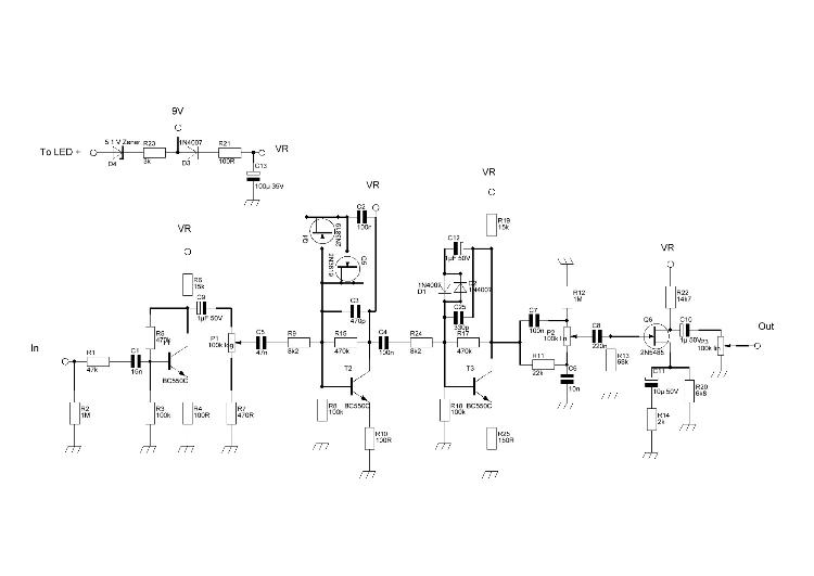
i took a look at this one based on a request. if you look carefully at the schematic it seems this is nothing more then a BMP with 2 main differences.
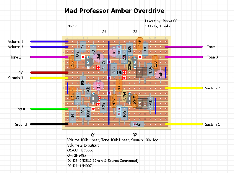
1 - MOSFET clipping in the first clipping stage 2 - FET in Q4 there are a few differences in values and a few added components, so i made a layout for it. it's not as neat or clean as my usual, and there's a few components that are standing as a result of trying to keep the size down as much as i could without having a massive amount of standing components. i'm going to try to make it neater and remove the standing components when i have a chance, but i don't know what thats's going to be. so in the meantime here's at least something so it can be built.  Edit: Incorrect layout removed, and corrected layout posted below. |
|
Hi Rocket!
Did you follow Hisseme's schematic? |
|
Another BMP? I think I hear something calling my name.

|
|
Administrator
|
I did. It was posted on DIYSB, if I remember correctly and have been verified so I went ahead and made the layout from it. I'm pretty sure this should be good to go, but if you see something off let me know and I'll fix it.
|
|
I hope I've looked at the right schematics (those posted on "requests"). Looking at your layout I think there are some problems around Q2, Q3 and Q4. For example D3 & 4 should go to the negative side of the 1uF cap instead of Q3's Collector. The 100n cap and 22K going to the tone should come from Q3's Collector and not the Base. Same problems on Q2. There is also a 100K res. from Q3 Base to ground missing. There should be cuts between Q4 & Q3 and the 68K res should go from Q4 gate to ground instead of Tone 2.
|
|
Administrator
|
Woops. That's what I get for making the layout when I couldn't sleep. I'll fix it later. I should have time when I get home to fix it.
|
|
Cool. I would double check the whole thing. There are a few cuts missing and a few other mistakes.
|
|
Administrator
|
This post was updated on .
i had some time tonight and needed to some something to clear my head for a bit, so i took a look at this again, and pretty sure it's good to go now. just need someone to double check it to be sure.
schematic 
|
|
Hi Rocket.
There is a 100K res missing from Q3's Base to ground. The 100n cap from Q3's Collector should be connected to Tone 3. There's also a cut missing between Q3's Base and Q4's Source. After that it should be good to go! |
|
Judging by the schematic its almost exactly the same as the Fire Red Fuzz, including the 2N3819 mosfets for clipping and a 2N5485 at Q4. Substituting components one might just as well adapt IvIark's layout for the Fire Red Fuzz, in which case the only problem would be finding space to cram in the 330pf cap next to the 470K resistor in the 2nd clipping stage.
|
|
Administrator
|
Oop. Uploaded the wrong file. I fixed to after I caught both of those and I guess I forgot to reupload the image. I'll do it as soon as I get home from work.

|
|
Administrator
|
Ok, this is the correct layout i made last night. hopefully, NOW its right
  thanks for all the catches albru |
|
Am I seeing it correctly that there is no voltage going to the 1st clipping stage? Judging from the schematic it seems that even though there's no resistor going to the 1st clipping stage with voltage, there should be at least a jumper as there appears to be voltage going into that circuit part. Even the Fire Red Fuzz on which this circuit is based has a 10K supplying voltage to the collector of Q2
|
|
Administrator
|
You sure? It looks like, to me atleast, that the mosfets are in the signal path connecting to one side of the 470pF & 100nF. The other leg of the 100nF cap should be connected to Vr. I did notice though that when looking at the schematic that the same leg of the mosfets that is connected to the 100nF cap is shown going to the left to another point, but there's nothing there, so I assume it just goes to the 100nF cap, since there's no marking for Vr. Which then asks, where does it go?
|
 http://guitar-fx-layouts.42897.x6.nabble.com/file/n18990/Amber_Overdrive.jpg Judging by the schematic there should be voltage coming in at the junction where 100n, 470p, 470K and the collector of Q2 meet. This is where Fire Red Fuzz layout has a 10K bringing in voltage. Maybe its my lack of electronics background, but now, no matter how hard I stare, I just don't see it happening. The voltage track stops at the 15K resistor going to Q3. To me it seems the cut right to that 15 resistor should be moved to the right, probably underneath D3, so a connection can be made to 4 tracks lower, probably between 100n and 470K. At least, that is how it looks to me. If you think I'm missing something I would love to learn how I was wrong. |
|
Administrator
|
I see it. There was a link that I must have deleted by mistake. No idea where my mind is.......This is quite embarrassing.
|
Re: Mad Professor Amber Overdrive
|
Lol dude don't even worry about it. It can't be worse than my VMT layout that I'm still not sure is correct.
Through all the worry and pain we move on
|
|
Administrator
|
one more time around the sun we go again.... sorry been listening to the last mastodon album a lot lately and it was the last song i heard as i got out of my car today.
added the missing link, removed a cut, and moved a cap, and should be alright. still not sure where the other connection should be on that side of the mosfet clippers. 
|
|
I listened to a demo of this today. Love this OD. This one has made the radar.
Thanks Rocket88!!  BTW, I see you made the jump to the newer DIYLC. Like it better than the older? Cheers Chris
Yeah, 220, 221. Whatever it takes.
|
|
Administrator
|
haha, thanks man. i actually have always used the V3. there's stupid quarks about V2 that piss miss off so i've just stuck to V3, and been trying to figure out how to get the V2 components into it, but so far that's been a no go.
|
«
Return to Booster, OD, Fuzz, Distortion
|
1 view|%1 views
| Free forum by Nabble | Edit this page |

