Madbean NomNom with Depth and LERA
12

12
|
This post was updated on .
10/27/2018 update: New layout verified (original layout probably ok too)
Can use either matched DSG or DGS jfets. (2n5952, 2n5457, 2sk246 all worked well) The *** caps to the right of the 3u3 are optional "placeholders". If you don't have a 3u3 non polar, you can use 3 or 4 non polar MLCC type to get close to the 3u3. Like three 1u and a 330n. verified 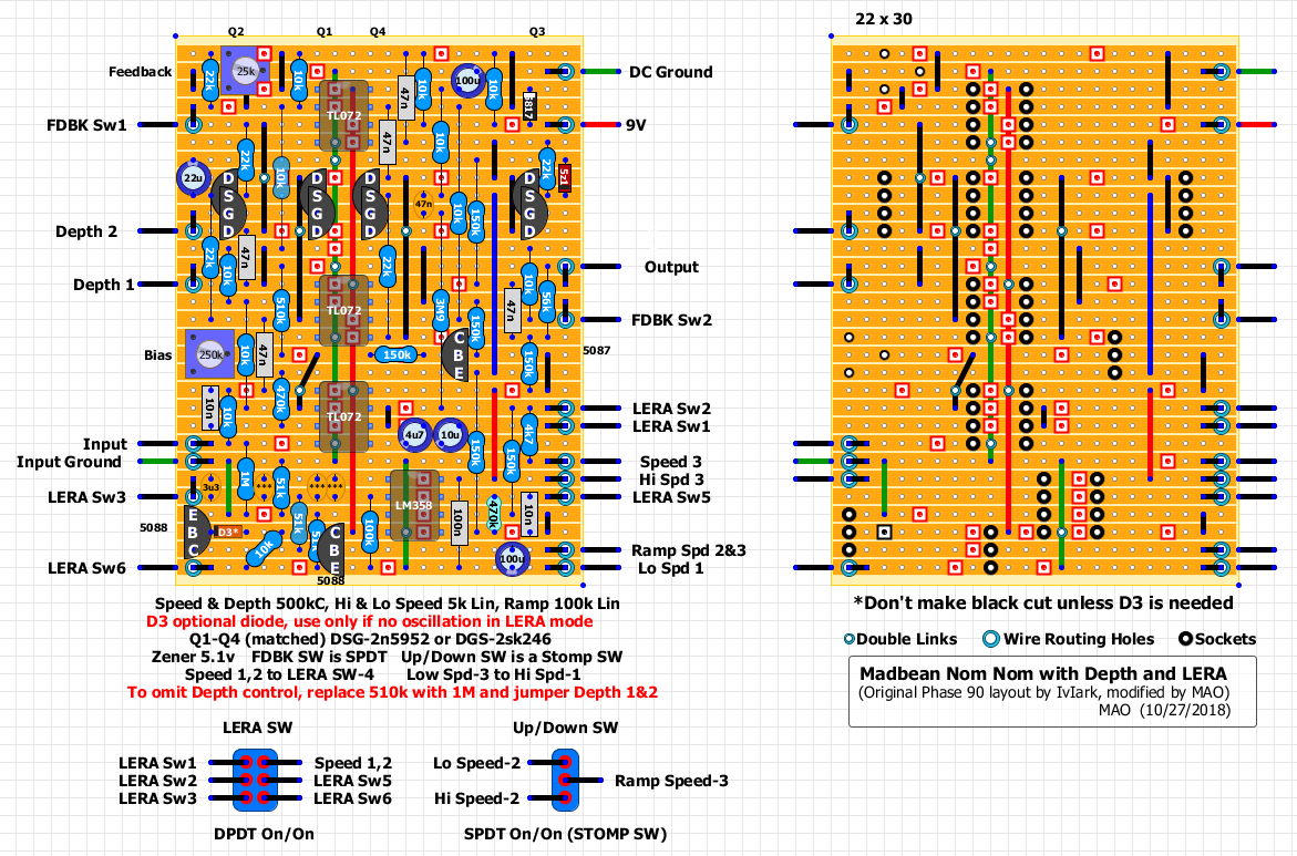 10/26/2018 update: layout was drawn for 2n5952 jfets. You'll need to reverse them if using 2n5457s. Corrected Ramp Speed connections per this request/discussion RG Keen's LERA, I've modified IvIark's original Phase 90 layout to NomNom specs and added a switchable LERA. See NomNom and Phase 90 LERA details here: Madbean's NomNom RG Keen's Phase 90 with LERA 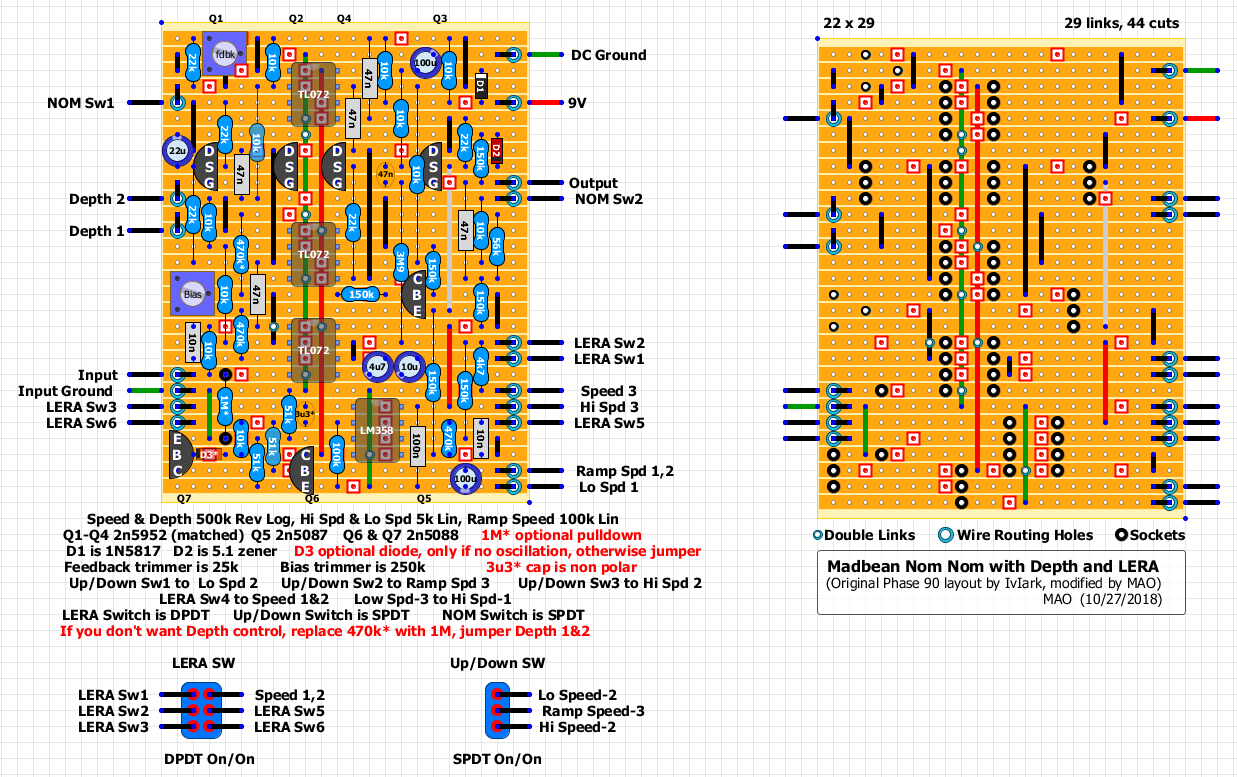 Here is the NomNom without the LERA. 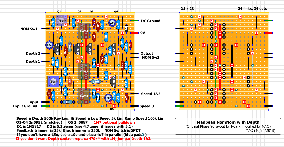 And here is the Madbean matcher as noted in the NomNom build doc, drawn for 2n5952 jfets, reverse it if using 2n5457s. 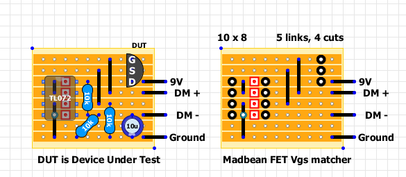
1978 Gibson Les Paul Standard, Cherry Sunburst
|
|
Hey MAO.. Thank you! We just started discussing the LERA a week or so ago, and now we're looking at a Phase90 with a LERA integrated into the circuit.. Your efforts here are sincerely appreciated and are plain awesome =)
Now to annoy the knowledgable with a question.. Could someone take a minute to explain to me the difference between the various inputs and grounds in this circuit? I see the different colored jumpers in this circuit, and I've seen circuits like the Ludwig PhaseII and the SchumannPLL that utilize various grounds and inputs.. any info or resources on how these are used would be great, before I dive into building something it's nice to have a grasp on the theory behind what's going on.. For me, anyway. Thanks again MAO! |
|
This post was updated on .
Thanks for the kind words!
I started color coding some of the links to help me keep track, especially if I know I'm not going to finish the layout in one sitting. I use Red for the 9v lines, Green for ground, and usually Blue for the Vb lines. (I used Grey on this layout though for the Vb) I'll also use Yellow if there is a 5v supply line and Grey if there is a negative 9v line. Again, the color coding is just to help me keep track when I'm drawing up the layouts. I also try to include a pad for the DC ground close to the 9v pad and another ground pad for the Input jack (to ground the enclosure). And I'll also leave "empty" color coded wires so if I need another off board grounding point or LED supply voltage I'll know where they are. And I'll add extra links and/or cuts and also angle components for a better fit and to avoid bending the legs underneath if possible.
1978 Gibson Les Paul Standard, Cherry Sunburst
|
|
So when wiring DC ground and Input ground, do both wire up like normal grounds.. there are just two of them in this circuit?
Also, would it be possible to upload a larger image of the layouts? I'm having trouble reading the values, even when opening them up in a new tab by themselves. Thanks again, this is great. I'm gonna take a stab at this soon. |
|
Yes, grounds hook up as normal. I usually ground the input jack to the board and the output jack is grounded by the enclosure (not to the board as this may cause a ground loop)
Re-posted larger layout above.
1978 Gibson Les Paul Standard, Cherry Sunburst
|
|
Hey all,
It's been a bit since the layout in the OG post was created, has anyone taken a stab at the NomNom w/ LERA? I have everything I need but the matched quad of 2N5457s... where are people getting these from? Mouser has them for about 90 cents a pop. I'm weary of buying a large lot for fear of not receiving a subset of four that are closely-enough matched. How do you guys get your matched transistors?.. specifically 2N5457s? |
|
Honestly mate, order some adapter boards from Chromosphere, and buy a bunch of SMT 5457 and J201 JFETs.
You won't regret it! Cheaper, more reliable, and no need to fanny about measuring and matching. I was reluctant to go down this route, but I'm convert now. Smell the future! |
|
Is the idea here that SMT transistors (or JFETs specifically?) are much more accurate from one unit to the next regarding their properties? You're so confident that you don't bother measuring them when a build calls for matched transistors? That's impressive..
|
|
you've got my brain churning now... for some reason it didn't cross my mind that there are adapters for every SMT component:
http://www.futurlec.com/SMD_Adapters.shtml Do you think the repeatability and reliability from unit to unit is better across all SMT components vs. their through-hole counterparts? If buying a few of these adapters for every build and spending a couple extra bucks would mean that I get better and more predictable performance from the components, then I may jump ship and join your team! |
|
Administrator
|
i would avoid futurlec. they're shipping is beyond slow. chromespere is not just a nice guy, and a member of the diy community, but he's got really great quality parts and relatively inexpensive.
|
|
Thanks for the advice Rocket.. could you provide a link? I had trouble finding his site via Google.
Re: my thoughts on smt vs. thru-hole in the previous post, is that all along the right lines? |
|
Administrator
|
|
SMDs are definitely the way to go at the moment, however I have found they measure all over the place. I would suggest ordering more than just a few.
I purchased 100 SMD 2n5457s from Mouser ($14.70) and so far have 3 matched quads with about 40 more to measure. (And about the same results with the SMD J201s from Mouser). I'm sure I will have a couple more matched quads once I get through them all as I already have numerous matched pairs and a few triplets. I'm matching within 1% though, which may not be necessary. I think I read somewhere 5% would be within tolerance. Also, the SMDs are very tiny, measuring them and then soldering them to the adapter boards takes patience. After some trial and error, here is how I do it: I built the "Greatly imprived JFET matcher". I then inserted a bare solid 22 gauge wire into the appropriate D S G sockets, about 1/2 inch long. Then placed an SMD adapter board over the 3 wires , copper pad side up, and soldered the board to the 3 wires. Trimmed the tops of the wires protruding through the adapter board. This makes a nice little platform for measuring the SMDs. Now the hard part, picking up those tiny SMDs and getting them on the copper pads on the platform. I used a set of non magnetized forceps to drop the SMD on the platform, then used my thumb to slide it over and hold it in place on the copper pads. Took the readings, then placed the SMD on a lined sheet of paper jotting down the readings on the same line. Then repeat the measuring process over and over using a different line on the paper for each different measurement until I got a matched quad. Since I had 100 to measure, I kept going until I found 3 matched quads, then had had enough and quit. I then took clear tape and taped each of the measured SMDs to the paper next to their readings so I can continue measuring and matching the rest at a later date without having to start over. I folded the paper up with the SMDs taped in place and stored the folded paper in the static free envelope they came in. After measuring the winners a 2nd time to be sure they were matched, I then used locking forceps to hold the SMDs in place while soldering them to their adapter boards. I used the same "platform" trick to hold the adapter boards in place while soldering. You end up with the SMD soldered to the adapter board which is already soldered to the 22 gauge wire "pins" so it's ready to be inserted into your build's sockets. Takes so time, but really not that hard once you figure out how to pickup and hold the little buggers in place. That being said, assuming I only get 6 well-matched quads (within 1%) out of the 100 purchased, with shipping costs, the cost of the adapter boards, and the "excess" unmatched smds, probably costs about 90 cents a piece to match the quads yourself. But you would also end up with another 76 2n5457s to use on some other builds.
1978 Gibson Les Paul Standard, Cherry Sunburst
|
|
Here's a picture of the measurements I took to give you an idea of the ranges. There's about 60 smds measured.
The 1st 3 digits next to each SMD is the Vp, I also measured the Idss on some of those that were matched by the Vp. That's the 1.xxx numbers off to the right. (or maybe vice versa) Looks like I matched 3 quads measuring 309, 242 and 229. I did not check to see how the NomNom sounded with 4 random SMDs, but it sounded great with the matched quad. 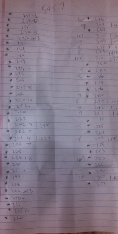
1978 Gibson Les Paul Standard, Cherry Sunburst
|
|
In reply to this post by MAO
Has anyone built this? i built it today and it doesn't work. i'm sure it has something to do with my wiring. the information for wiring is kinda confusing. it states that the hi/lo switch is spdt but that is the only mention of it unless i'm going cross eyed from looking at it so much. also has a up/down switch but doesn't
state what type etc. |
|
Wow, I forgot all about this one. And no through holes for the wiring, it's been a while for sure.
Sorry for any confusion, sure it made sense to me at the time...and probably only me :0) I don't recall actually building it, but I'll look it over tonight and get back to you.
1978 Gibson Les Paul Standard, Cherry Sunburst
|
|
That would be awesome mao. thanks
|
|
In reply to this post by MAO
ok, there is a typo, the hi/lo switch is actually the up/down switch. There is no hi/lo switch.
Other than that typo and the Depth control mod, it appears the layout matches the Nom Nom and LERA schematics. It looks like I added a switch to select either the LERA or original LFO, which I called the LERA SW. When lugs 1&2 and 4&5 are engaged, the LERA is bypassed and the original LFO and it's SPEED pot are active. When lugs 2&3 and 5&6 are engaged, the LERA and the three Lo/Hi/Ramp Speed pots are active, the original SPEED pot is then disconnected. Here is a picture of the LERA and UP/Down Switch connections  Are you getting the regular phase with the LERA SW off? (lugs 1&2 and 4&5 connected)
1978 Gibson Les Paul Standard, Cherry Sunburst
|
Re: Madbean NomNom with Depth and LERA
|
What is a LERA?
|
|
LERA - the Leslie (tm) Effect Rotor Adapter
Apparently the LERA will allow you to alter the LFO Speed at different ramp up & ramp down rates. But I think you need to repeatedly step on a stomp switch to change between ramping up and ramping down the speed control. I think today I would prefer using an envelope follower to alter a Speed control with picking dynamics, rather than tap dancing on a stomp switch...but I'm not as young as I used to be :0)
1978 Gibson Les Paul Standard, Cherry Sunburst
|
«
Return to Phasor, Chorus, Flanger, Termolo, Vibrato
|
1 view|%1 views
| Free forum by Nabble | Edit this page |

