Modified Sparkle Motion

classic Classic list List threaded Threaded
9 messages Options
KT
Reply | Threaded
Open this post in threaded view
|

Modified Sparkle Motion

KT
This post was updated on .
Hello,
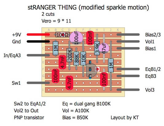
I wanted to built a Sparkle Motion without input atten. Also I wanted to use a PNP trannie without using a charge pump etc. I have put it on breadboard and had to adjust some resistor values to make the bias work but now it sounds nice. However I've not compared it with my other rangmaster builds yet. It is the first time I used DIYLC so I'm happy to get comments to improve.
Reply | Threaded
Open this post in threaded view
|

Re: Modified Sparkle Motion

Neil mcNasty
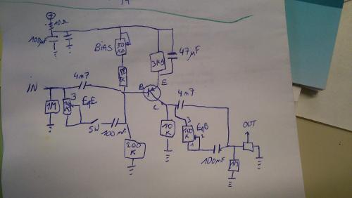
A Schematic would be great in order to see how the circuit is supposed to be.
Otherwise we will have to "draw it up in our minds" while decoding the vero, and that can be a bit difficult...
KT
Reply | Threaded
Open this post in threaded view
|

Re: Modified Sparkle Motion

KT
hi Neil,
here is original: http://smallsoundbigsound.blogspot.be/2011/05/sparkle-motion-schematic-and-updates.html

I'll take a picture of my drawing with the modifications when I'm home.
Reply | Threaded
Open this post in threaded view
|

Re: Modified Sparkle Motion

Ciaran Haslett
In reply to this post by KT
If it's more general comments you're after...

Ditch the colour bands.  Makes the values hard to read.
Update any rare values to more modern ones.  45uF???  Change that to 47uF and it'll save a load of questions lol
Add a board size/cuts/links count.  Again, just saves questions.

More specific to this layout...PNP so this is a positive ground circuit?  Not specified on the layout the Red/Black wires just confuse people.  If Black = GND and Red = -9V then your 100uF filter cap is the wrong way around.
KT
Reply | Threaded
Open this post in threaded view
|

Re: Modified Sparkle Motion

KT
Hi Ciaran, thanks for the comments. PNP but negative ground, like the fuzz factory for example. So red is +9. I'll update this according to the comments.
KT
Reply | Threaded
Open this post in threaded view
|

Re: Modified Sparkle Motion

KT
Updated vero layout and added schematic
Reply | Threaded
Open this post in threaded view
|

Re: Modified Sparkle Motion

Neil mcNasty
Cool!
Like the use of dual gang pot for the EQ.
Been using similar solutions for adjusting two gain-stages from one pot.
Looks like an interesting variant of a legendary circuit, gotta give this a go on the breadboard...

Looks like your layout is correct, and it is nice and compact...

The only (tiny) thing I would mention is:
You are using the symbols for ceramic disc caps, where I normally use the film cap symbols.
This is of course a personal preference, but when seeing a ceramic symbol, I expect to find a pf-value, and when seeing a film cap symbol I expect a nf-value.
This is something I adopted from the layouts we see on this site (there are some exceptions of course...) and something I find helps the tidiness of a layout.

Otherwise I would say congratulations on designing/tweaking your own circuit and thanks for sharing it!
Highly appreciated!
KT
Reply | Threaded
Open this post in threaded view
|

Re: Modified Sparkle Motion

KT
Hi Neil, thanks for the comments. Yes you should try this on the breadboard, it is easy and I think necessary to get most out of the bias knob in this circuit. Cause I first used the bias resistors from the sparkle motion and although I got a nice boost, my transistor didn't mis-bias enough with those values. You could of course also mis-bias it at the emitter like Miro did in his FYA Garagemaster, i didn't compare both methods.
Reply | Threaded
Open this post in threaded view
|

Re: Modified Sparkle Motion

Ciaran Haslett
Looking great KT.  Cheers for the share