Mudhoney Build Problems

classic Classic list List threaded Threaded
9 messages Options
Reply | Threaded
Open this post in threaded view
|

Mudhoney Build Problems

jwroper
Hi,

I'm having some real problems building the T-rex Mudhoney. I've built it 3 times now and the last 2 have had the same issue:

When i use the audio probe on the output of the pedal I can hear the effect and everything works perfectly. However when I try it on my test rig or boxed up, no output at all.

- I hear sound fine when bypassed
- The LED lights when I engage the effect
- When I engage the pedal I can hear the effect working OK with an audio probe on the output jack.

All points of ground pass the continuity test, if I put a probe on the ground output of the board that's fine too. The whole bottom row of the board passes the test. Anything else other than grounding that could be causing this? Why can I hear output from the probe and not from the jack?

Heres some pics of the wiring https://plus.google.com/photos/116241861790572354815/albums/5851159051084585457 

Really appreciate any suggestions, I've hit a brick wall with this one and I've got the enclosure all ready to go...so close... arrgggghhhh! Thanks guys!


Reply | Threaded
Open this post in threaded view
|

Re: Mudhoney Build Problems

IvIark
Administrator
But you're a Leeds fan
Reply | Threaded
Open this post in threaded view
|

Re: Mudhoney Build Problems

IvIark
Administrator
In reply to this post by jwroper
Just kidding, I responded on the layout post
Reply | Threaded
Open this post in threaded view
|

Re: Mudhoney Build Problems

jwroper
If I get this working I promise to change my avatar, hows that ;) Thanks Mark
Reply | Threaded
Open this post in threaded view
|

Re: Mudhoney Build Problems

Milkit
Right then, what you've done wrong is..............
;0)

(Sorry dude)
It's better to have it & not need it, than to need it & not have it!
Reply | Threaded
Open this post in threaded view
|

Re: Mudhoney Build Problems

Milkit
In reply to this post by jwroper
How have you wired the jack that's in the photo?  It looks like your battery minus is going to the tip, or is that the way the terminations on your jacks are orientated?  I use the switchcraft jacks from Farnell & that terminal (with your pp3 clip) is for the tip.
It's better to have it & not need it, than to need it & not have it!
Reply | Threaded
Open this post in threaded view
|

Re: Mudhoney Build Problems

Milkit
In reply to this post by jwroper


Not too sure if this'll help but,................................
It's better to have it & not need it, than to need it & not have it!
Reply | Threaded
Open this post in threaded view
|

Re: Mudhoney Build Problems

jwroper
OK thanks all, i'm going to check these points out tonight, again really appreciate it. Will let you know how I go... I think the board is OK what with it working with the audio probe but i guess the audio signal could be getting through but the ground part of the board might not be working?
Reply | Threaded
Open this post in threaded view
|

Re: Mudhoney Build Problems

jwroper
OK so it gets weirder...I was messing about with the ground connections, all fine. I changed the output jack, no change. It still worked with the audio probe, and I noticed that the only difference between that and the output jack in the box was the 100n greenie cap that was attached to the probe. I soldered the cap between the output from the 3DPDT and the output jack, and hey presto, it works! WTF! What would the cap be doing that would make it start working?

So its boxed and working, however I've still got a few issues that suggest something definitely isn't quite right. The tone knob seems to be reversed, is that correct for this build? (I.e. it gets brighter when turned to the left, darker to the right).
When the treble and gain are turned up in boost mode i get a shrill high pitched noise...
In non-boost mode the gain is a lot lower than in the mudhoney demo video.

I've got another mudhoney circuit that was having the same issues so I'll try that with a cap on the output to see if it solves it. On concern I've got is that when the effect is bypassed the signal will be going through the cap...will this affect it? I guess i could put the cap between the board output and the switch input...

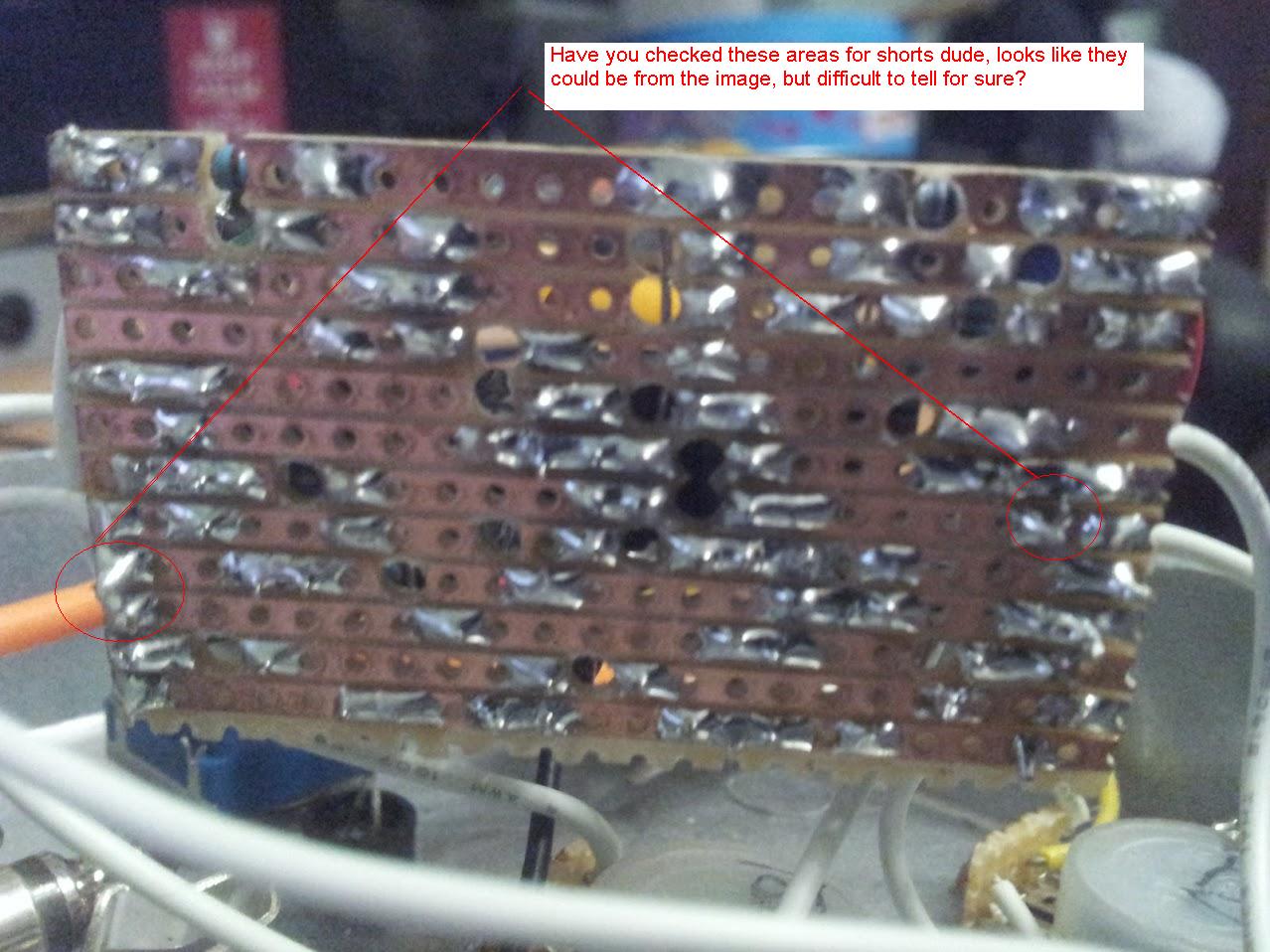
I've put some more pics up of what I've done in case my ramblings don't make sense...

https://plus.google.com/photos/116241861790572354815/albums/5851159051084585457

Thanks
Jack